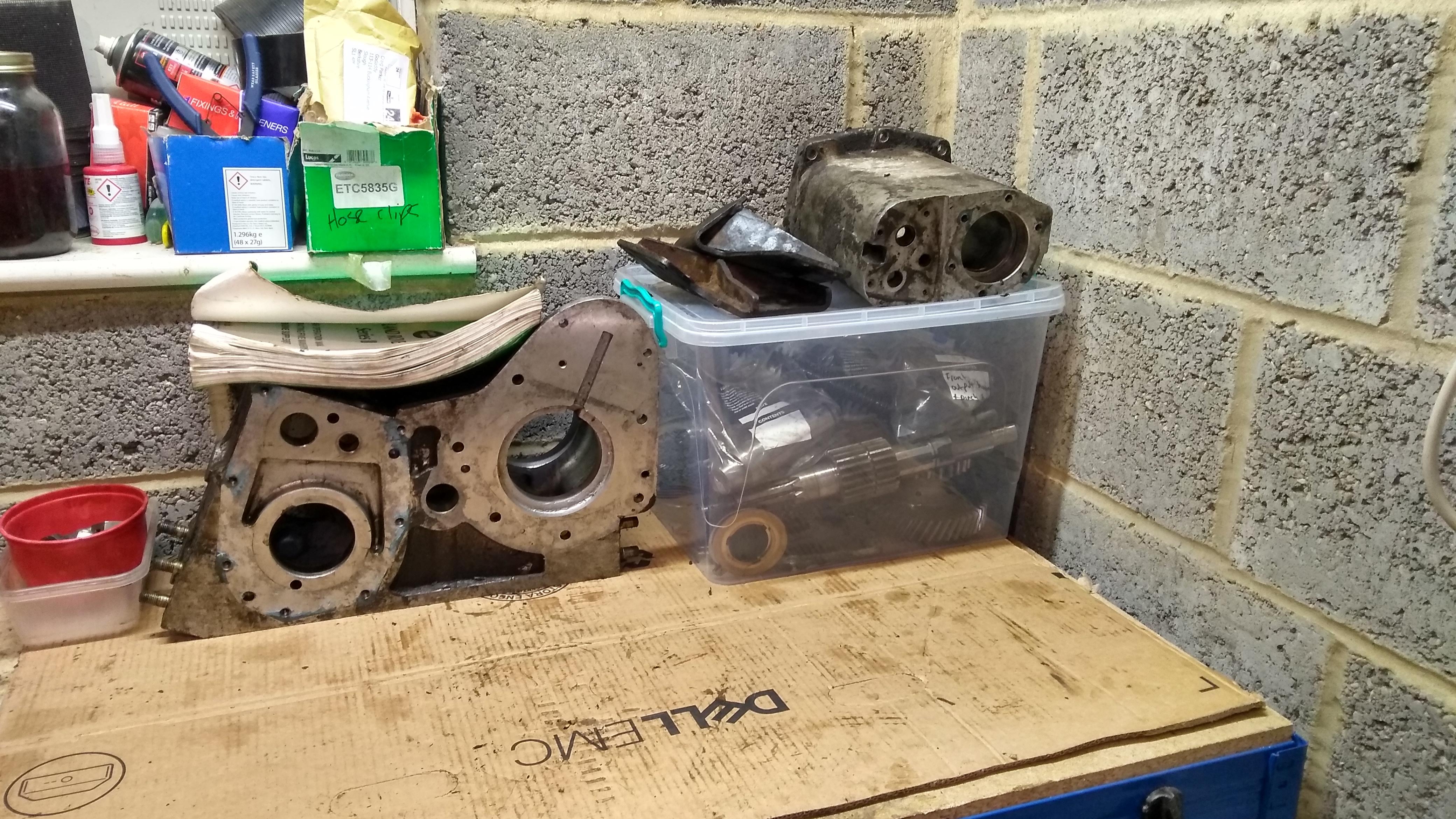
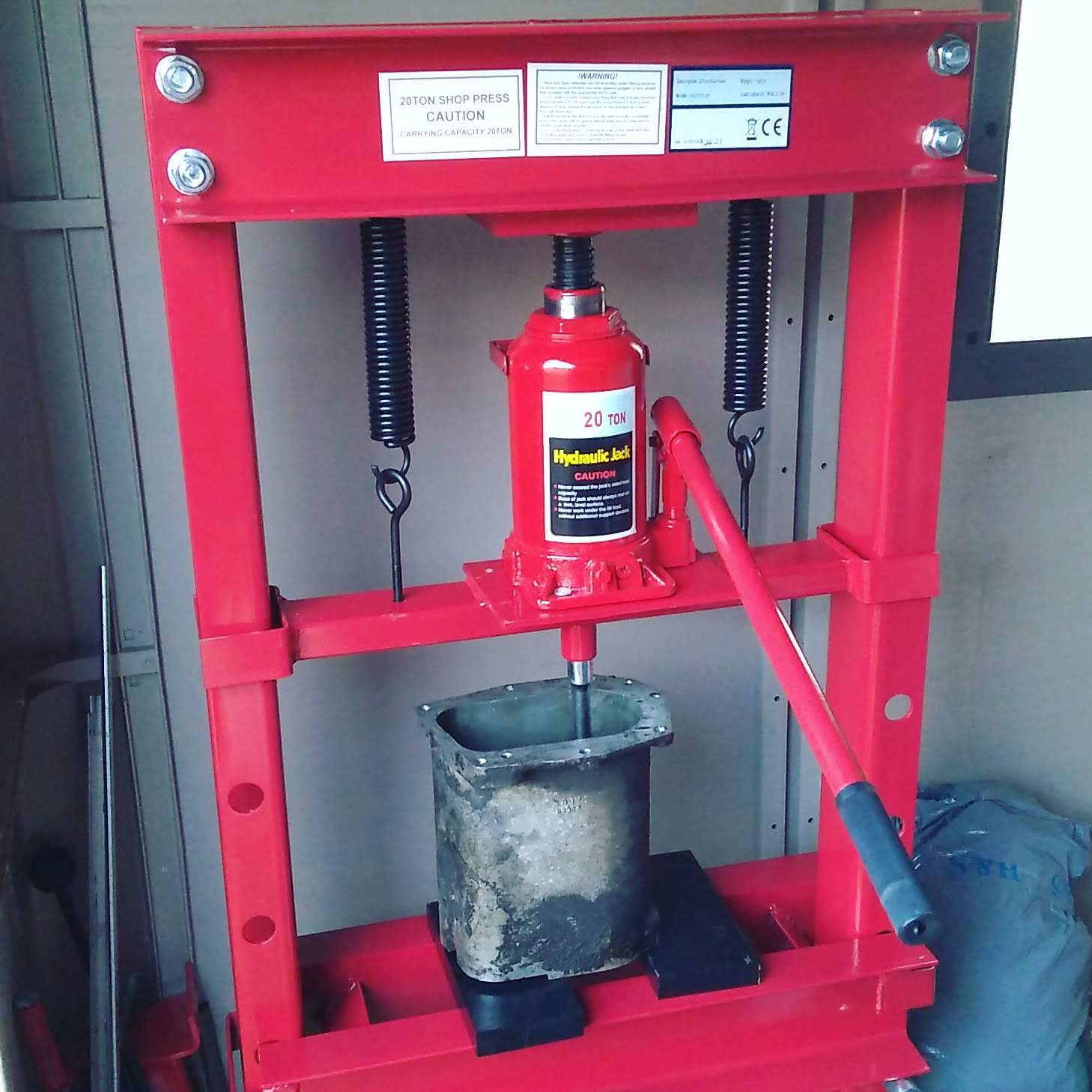
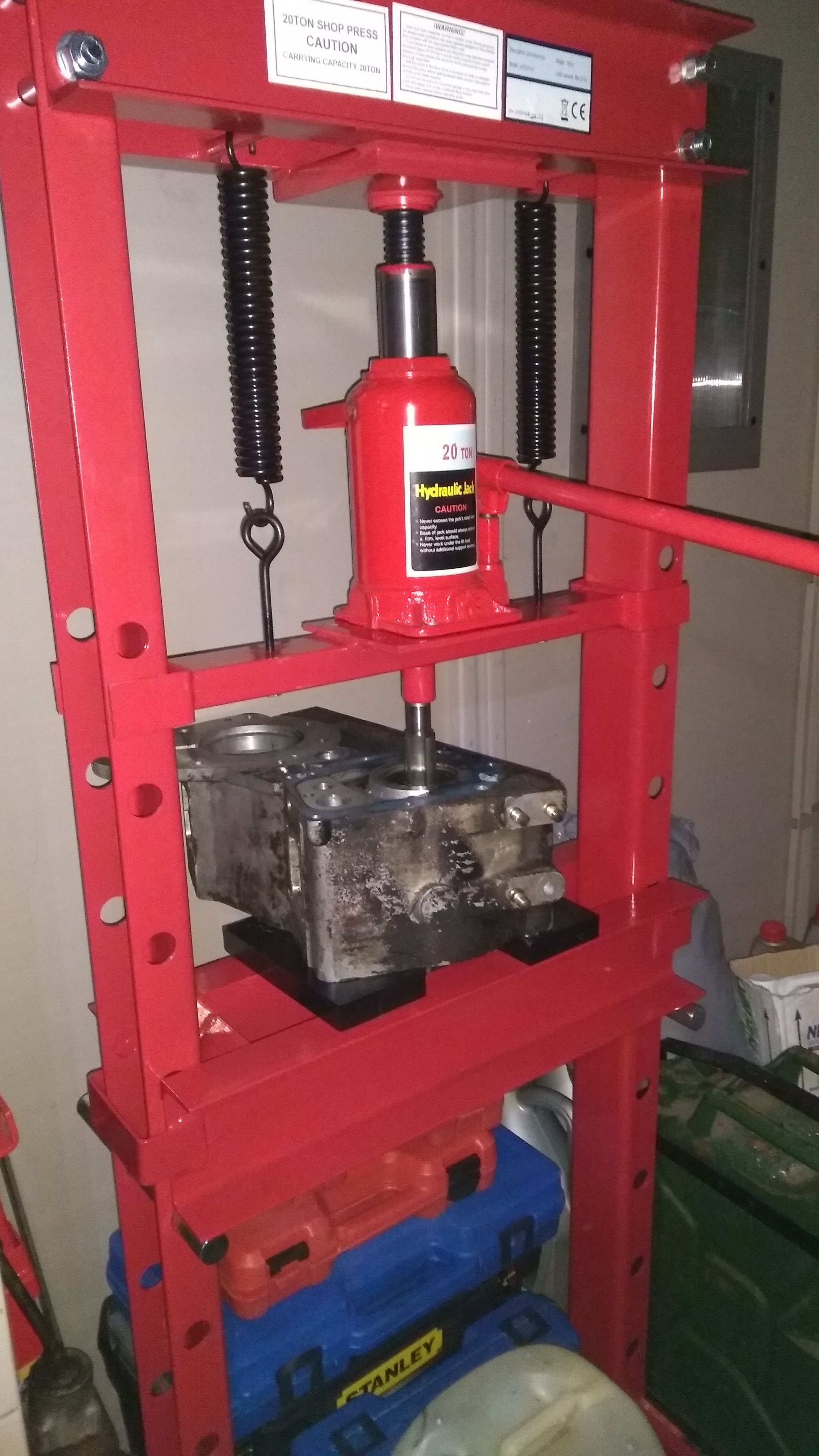
The gearbox rebuild finally continues! Though I have done some stuff since part 1. Mostly degrotting most of the parts removed and I also came to the conclusion that instead of finding an overdrive (because they go for silly money and would probably need a costly rebuild as well) I would get a high ratio transfer box kit from Ashcroft. This involves sending my transfer case off to be machined so it will accept the new gear set. I didn't want to just send mine off incase there were any issues so I did the sane normal thing and bought another transfer case from eBay. This one had the front/rear output shaft still in it that I had to remove to get it ready for shipping. So I got to disassemble that as a pre game for doing the complete transfer box. I just need to say, if you are going to do any gearbox/bearing stuff.. just get a press, you will thank yourself. Or at least have access to one. I got most of the aforementioned transfer case apart by hitting it with mallets, but then I ran into one bearing that would just not come off, no matter how much I hit it. So I bought a press. I did a whole bunch of research on what size to get and came to the conclusion that 20 ton was the best for a home mechanic and that I would want a floor standing one, as it provides more space for pressing and doesn't take up bench space which I'm lacking in. I just got one from eBay, nothing fancy but it does the job. It was £130, but so worth it, considering the rebuild kit for the gearbox is going to be more than that.. So anyway, onwards with the disassembly.
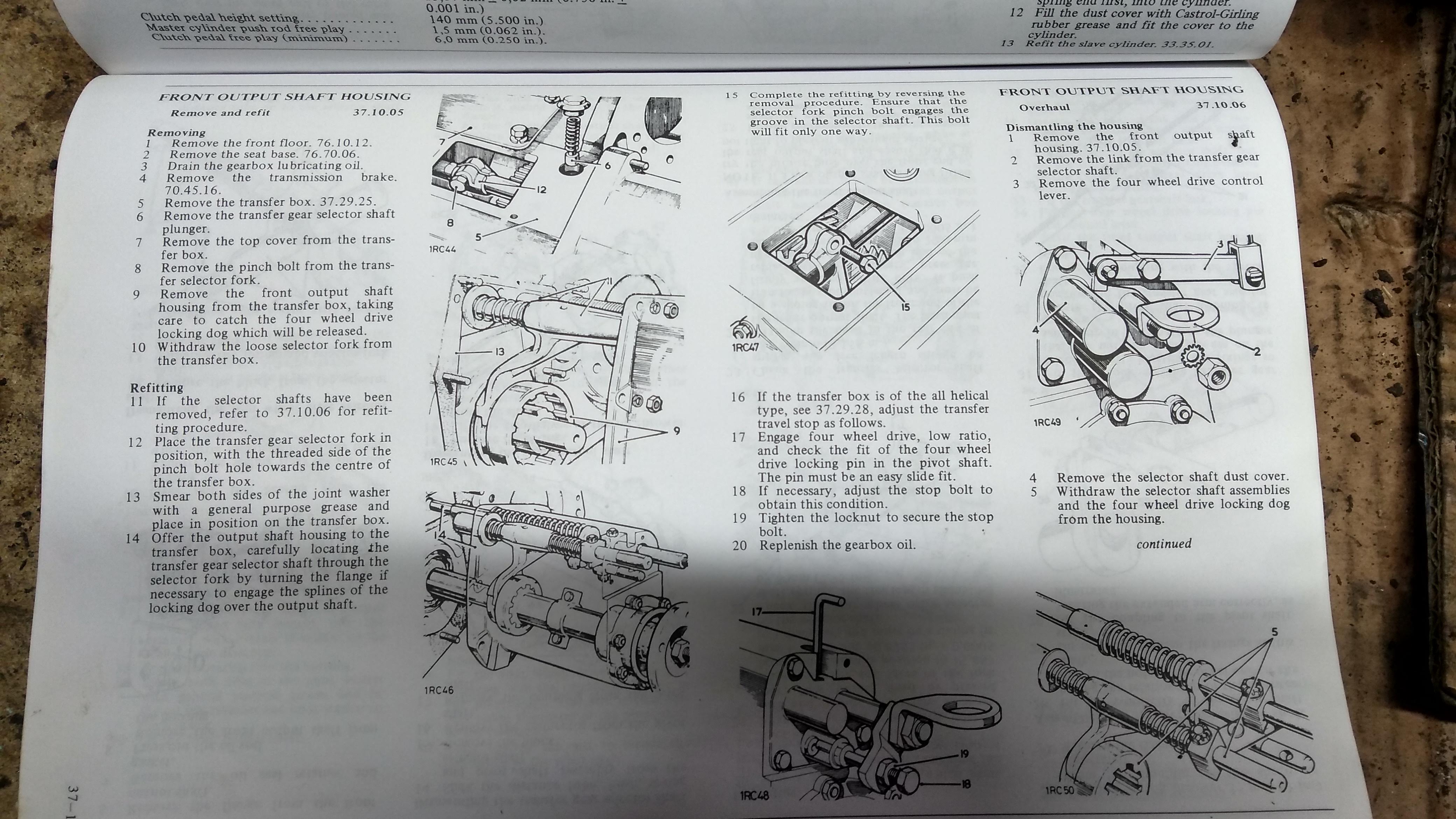
The simple looking instructions.
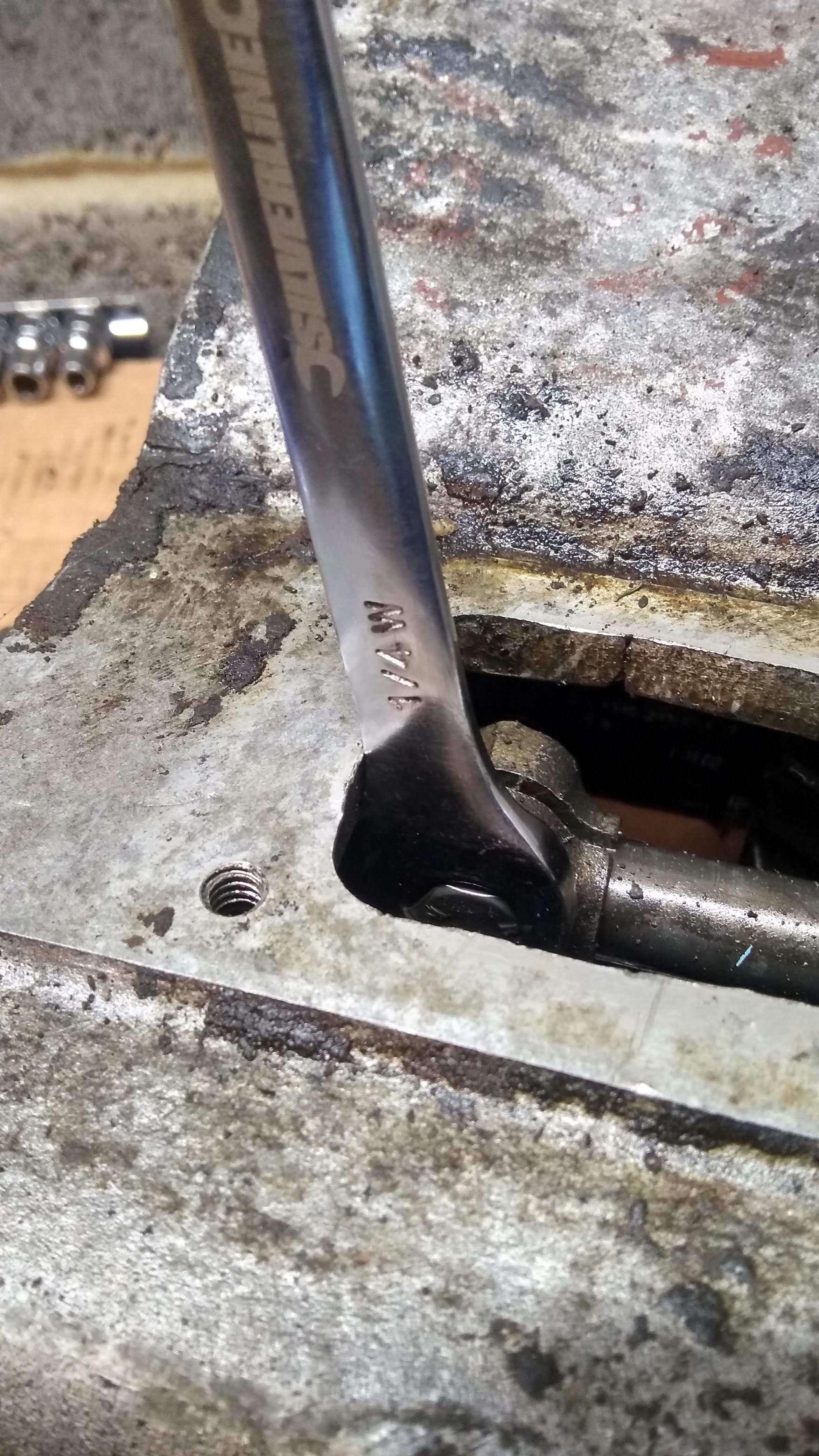
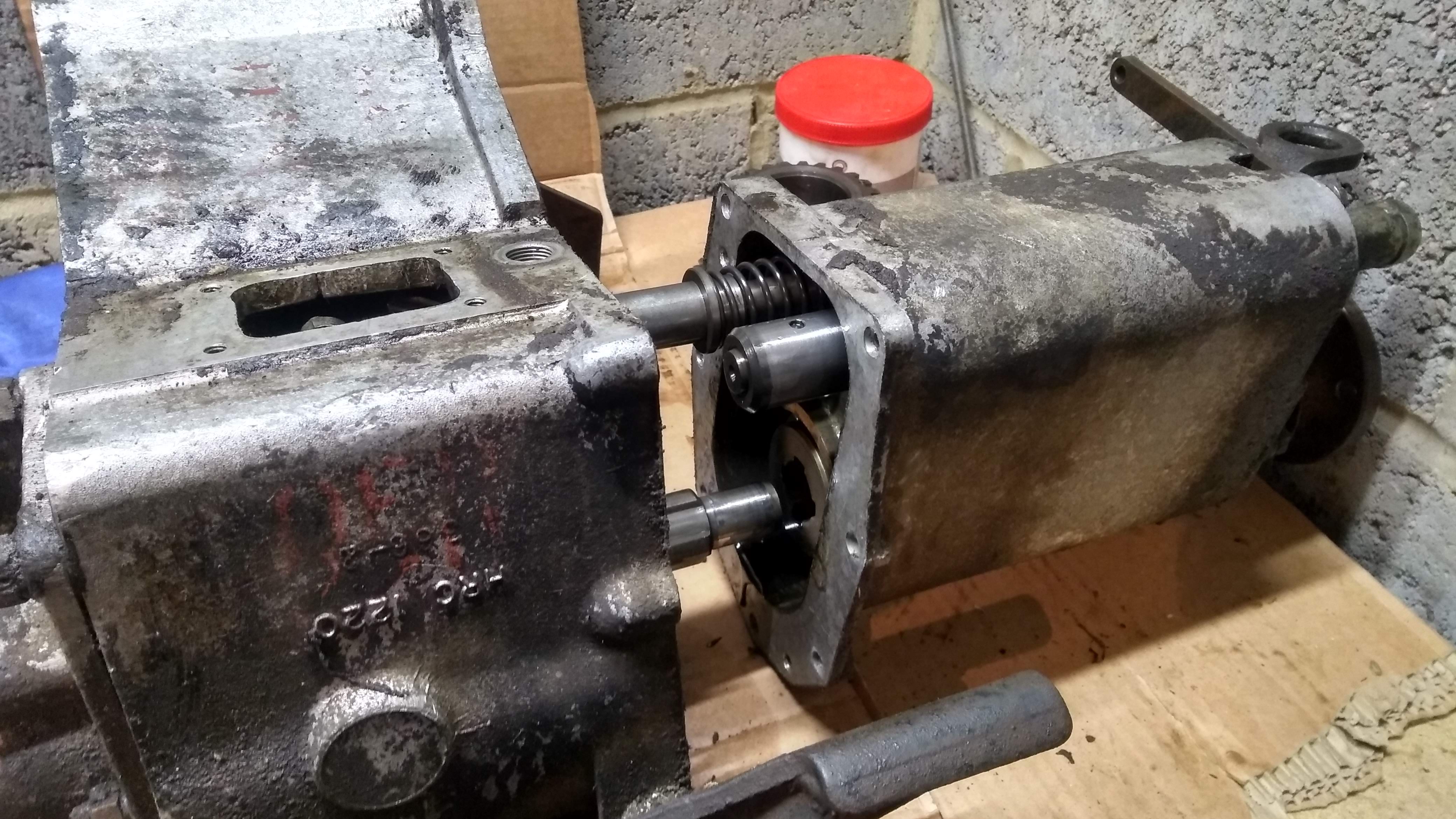
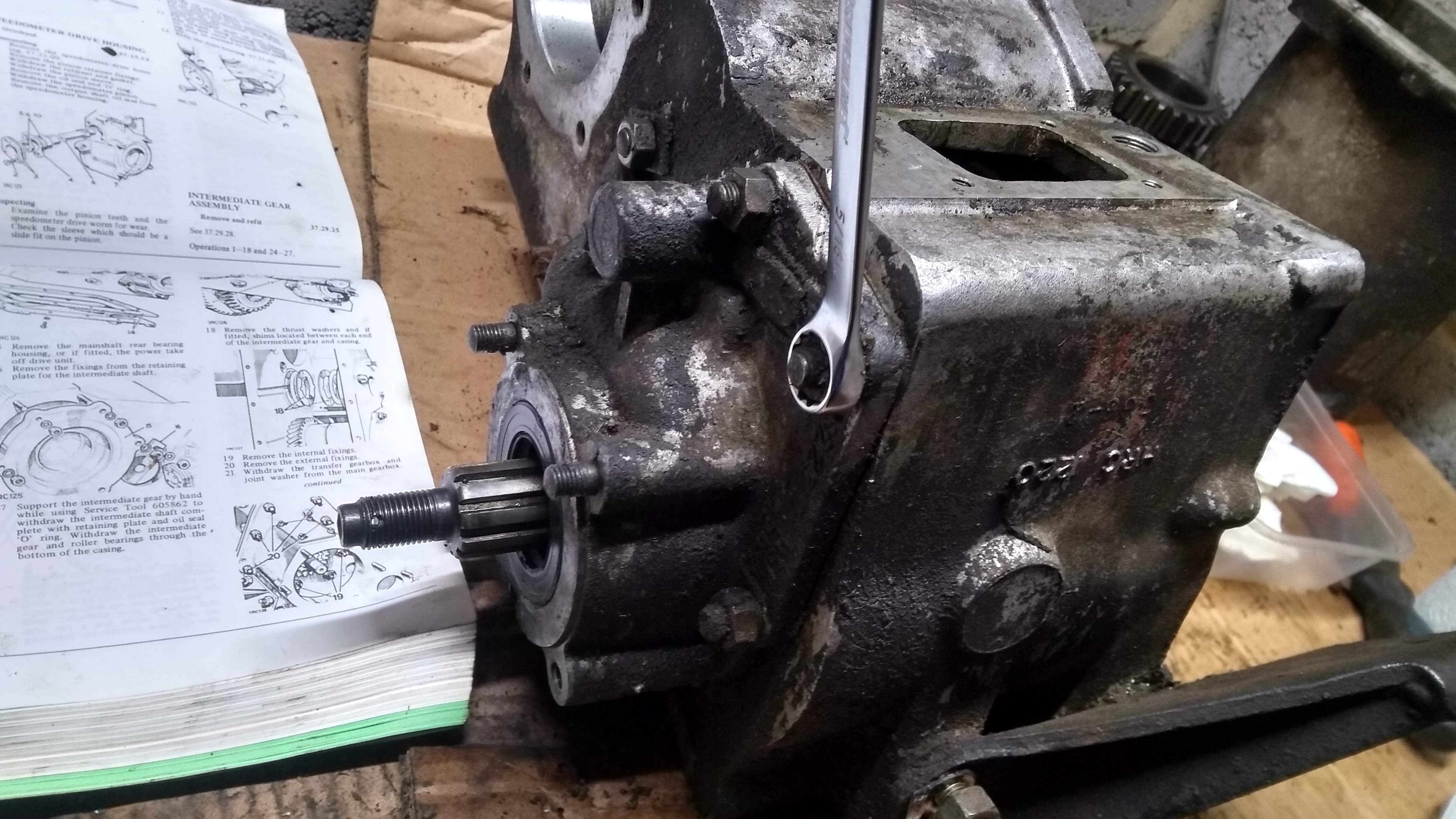
Firstly the pinch bolt that holds the selector fork to the shaft for hi/low needs to be removed, I had to tap the spanner with the mallet to free it off before it came undone easily, after that I just had to remove all the nuts holding the housing to the case. They are all whitworth, like everything on the gearbox so far. I should also say, get a set of whitworth spanners and sockets. As it's all you will use.
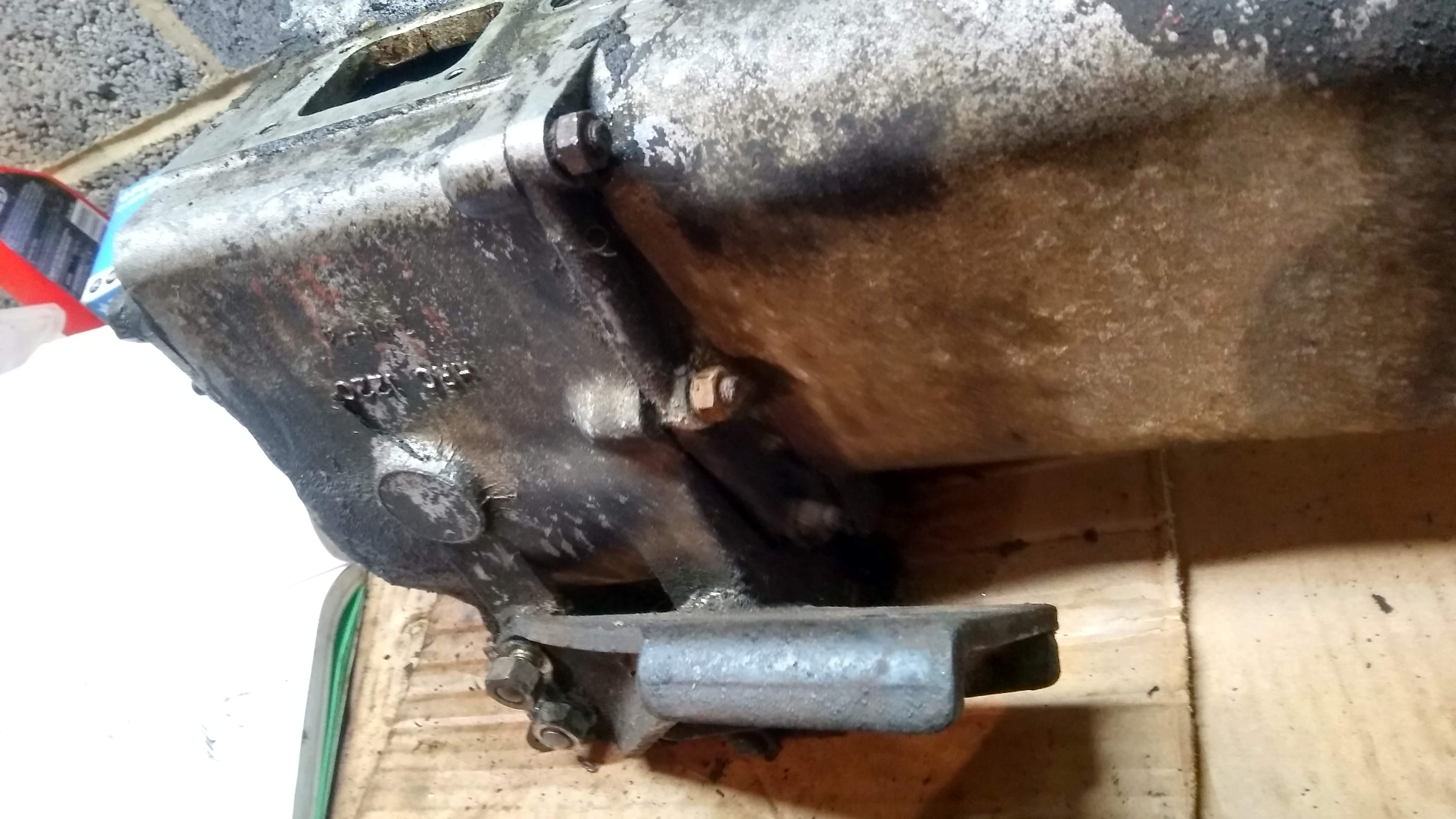
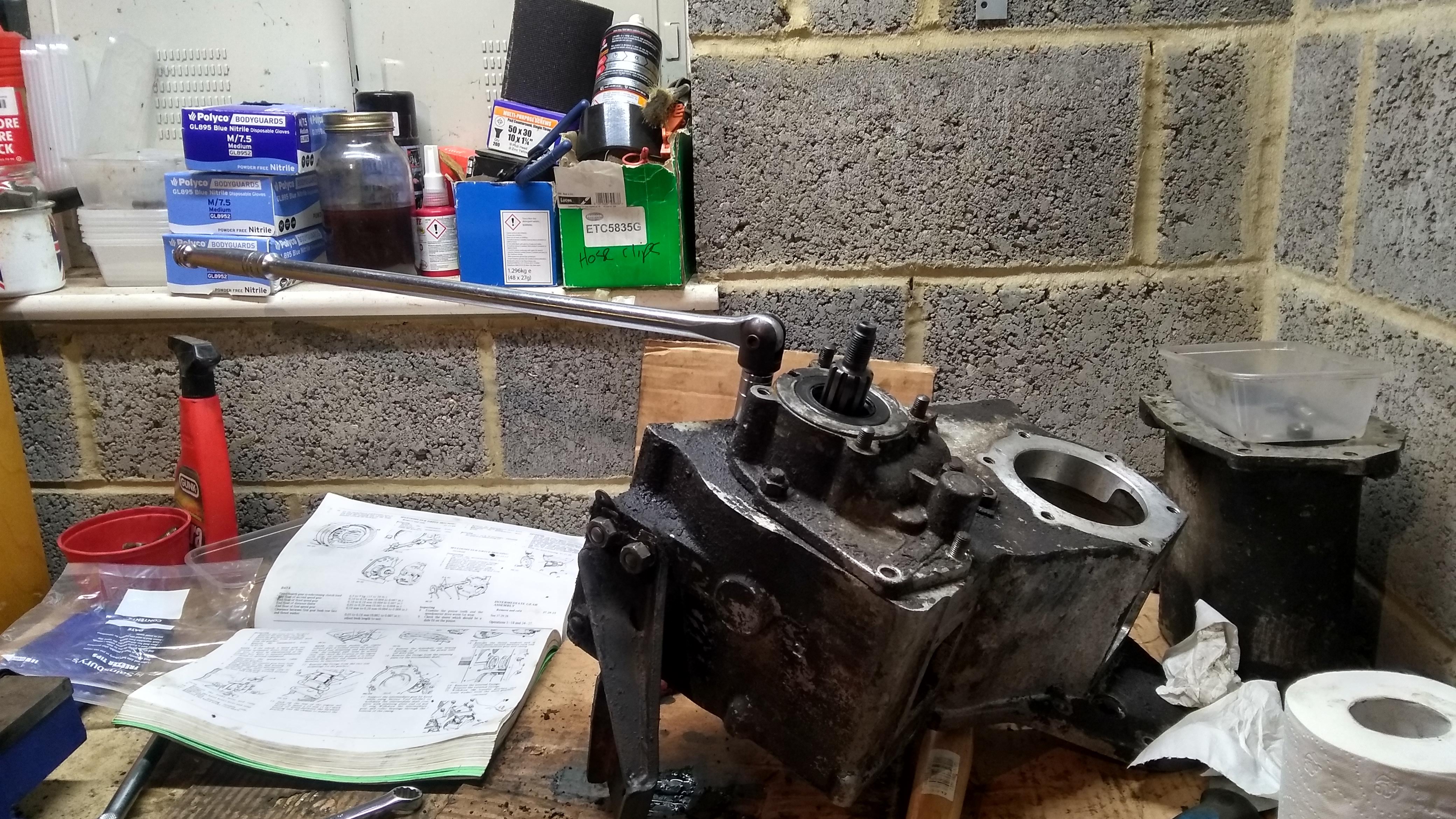
Once they are all removed (in my case most of the studs came out as well), the housing is just gently prised away from the transfer casing
You can then pull it completely apart, and remove the dog gear for 2wd/4wd selection.
The next step is to remove the ring from the end of the selector shaft that the red levers ball sits in. Though I found that this was on there tight.. so I had to put the casing back together slightly so I could get enough leverage to get it to loosen off. Next time I will make sure I loosen it off whilst the whole thing is still together..

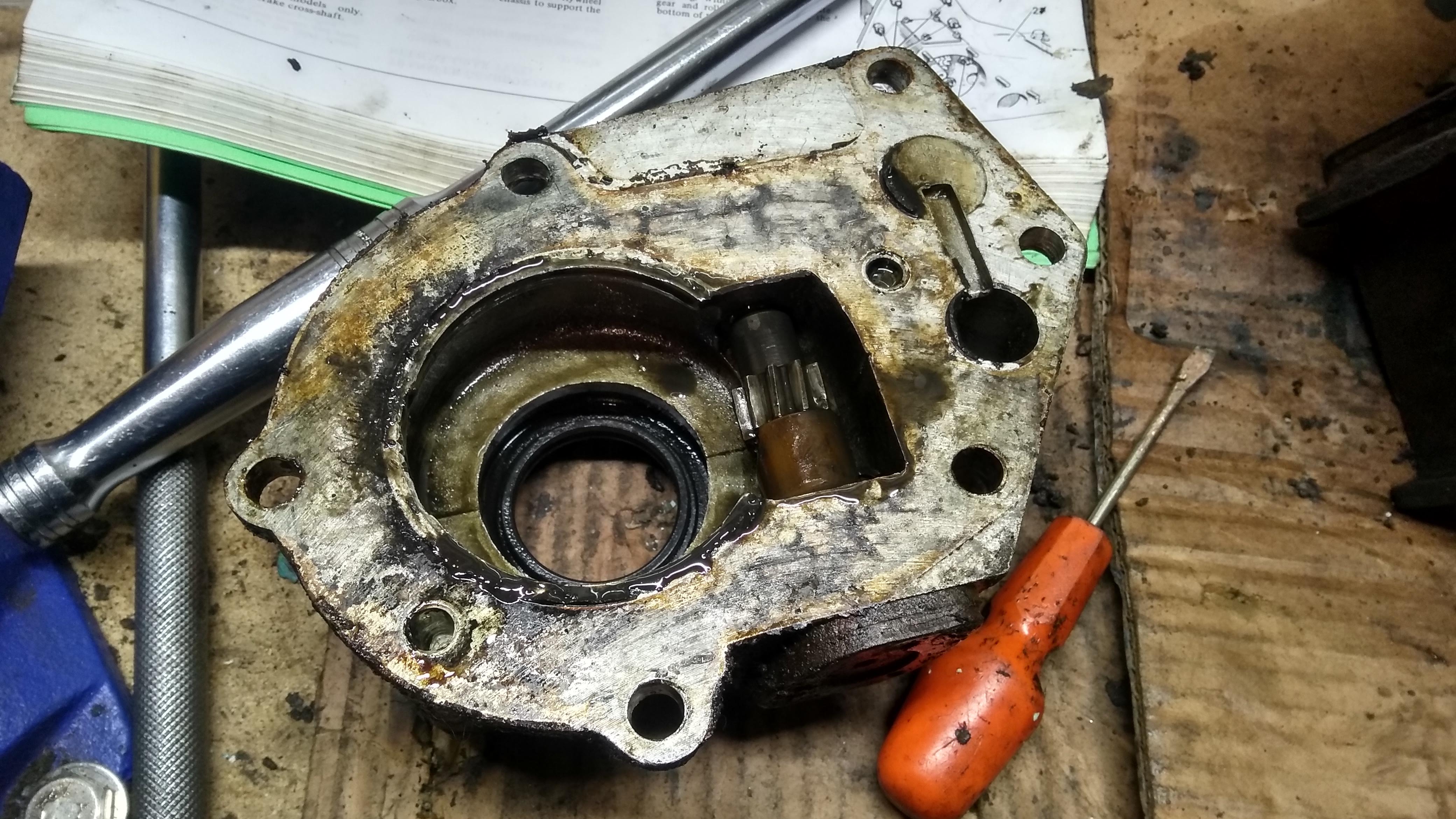
Once the nut is removed the ring bit just pulls off, you can then remove the cover for the selector rods. The rusty gunk in here takes me back to school and the smell of the trombone I had to learn to play.. I also removed the pivot arm for the 4wd locking pin, it's held in with one bolt.
The ends of the selector shafts are bit rusty. I believe this is a common issue where they rust up due to lack of use and then either get stuck or cause issues trying to change between high/low. I think this is the issue my own box has as sometimes it won't go back into high very well.
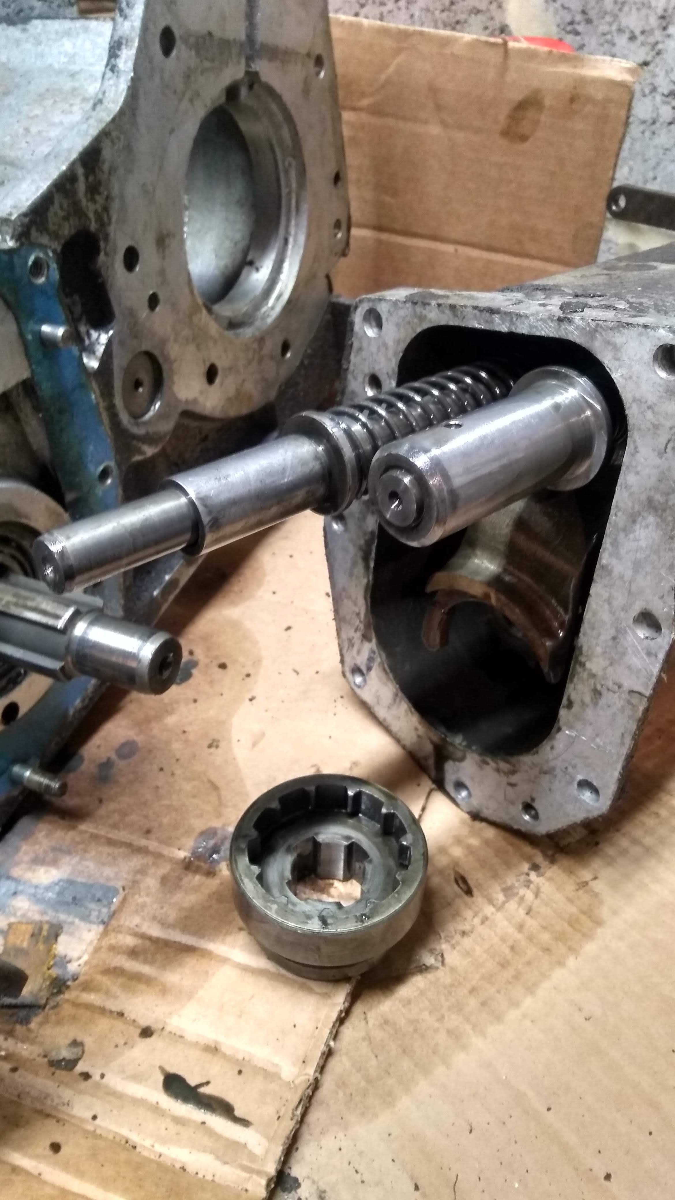
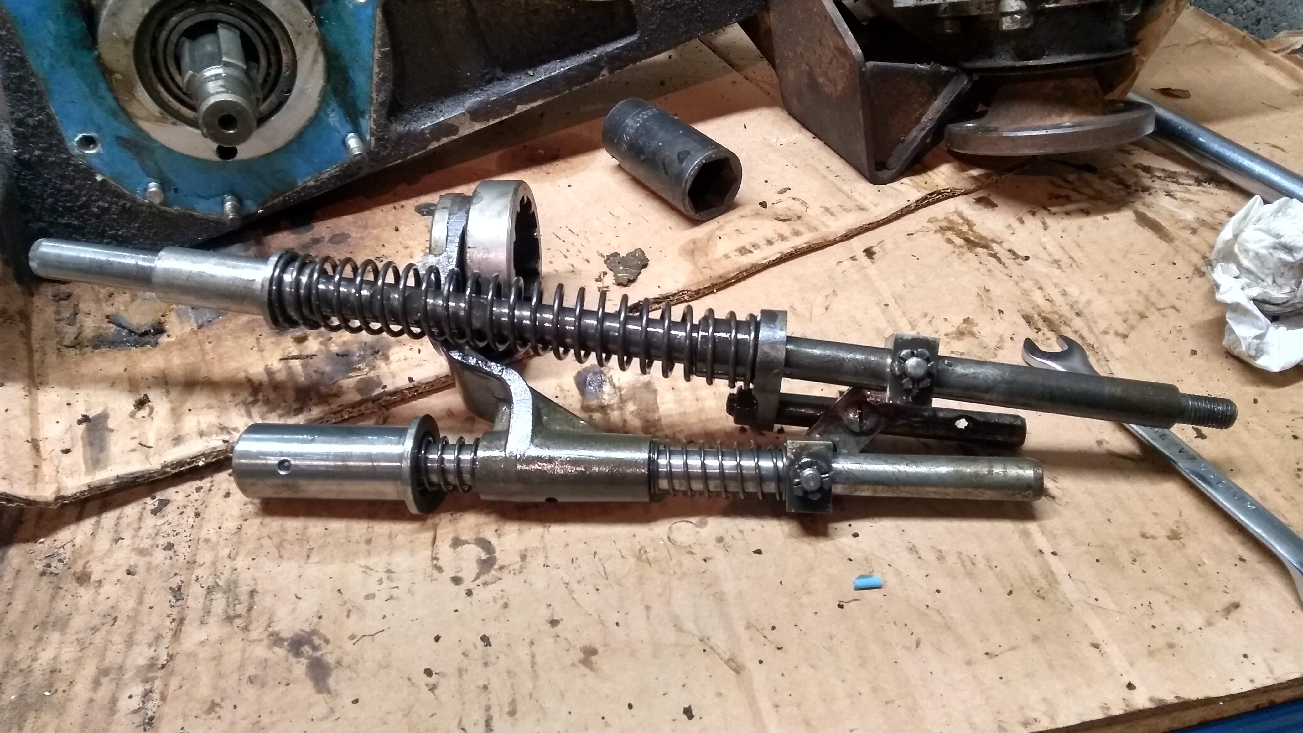
They will now mostly pull out of the housing, I did have to tap the end of the threaded one with the mallet slightly to get it to shift. Here they are in all their glory, along with the dog gear for 4wd. After playing with them on the bench I think I get how they work (though I could be wrong..).
When the red lever is forward, the dog is pushed rearward and is disengaged from the teeth on the front shaft (so it's in high range, 2wd). If you press down on the 4wd yellow lever, it pivots allowing the locking pin to come out of the shaft which then moves backwards under tension from the springs, this causes the dog gear to go backwards locking the shafts together. Then when the red lever is moved to low range, if 4wd isn't already engaged it would engage the dog, else it just moves the low range gear into selection in the transfer case. Then when the red lever is returned to the high range location, to moves the low range gear out of selection and locks it against the high gear (to hold high gear to the shaft, as otherwise it can spin freely), and it moves the dog gear forwards to disengage 4wd. As the locking pin is under tension of the spring on it's shaft, when the hole slides under the pin it allows it to drop into it. The two output shafts can spin independently when not locked together due to a bushing in the end of the front housing shaft that the transfer cases output shaft slots into. It all makes more sense when it's in front of you.
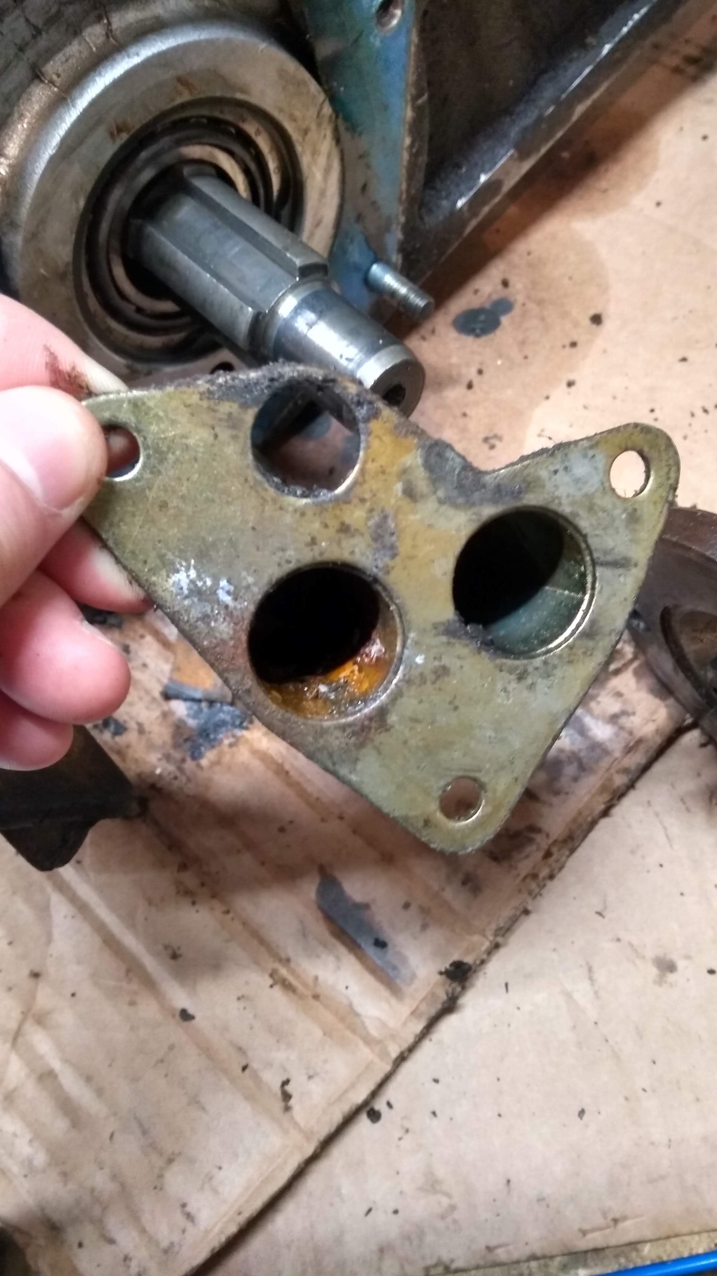
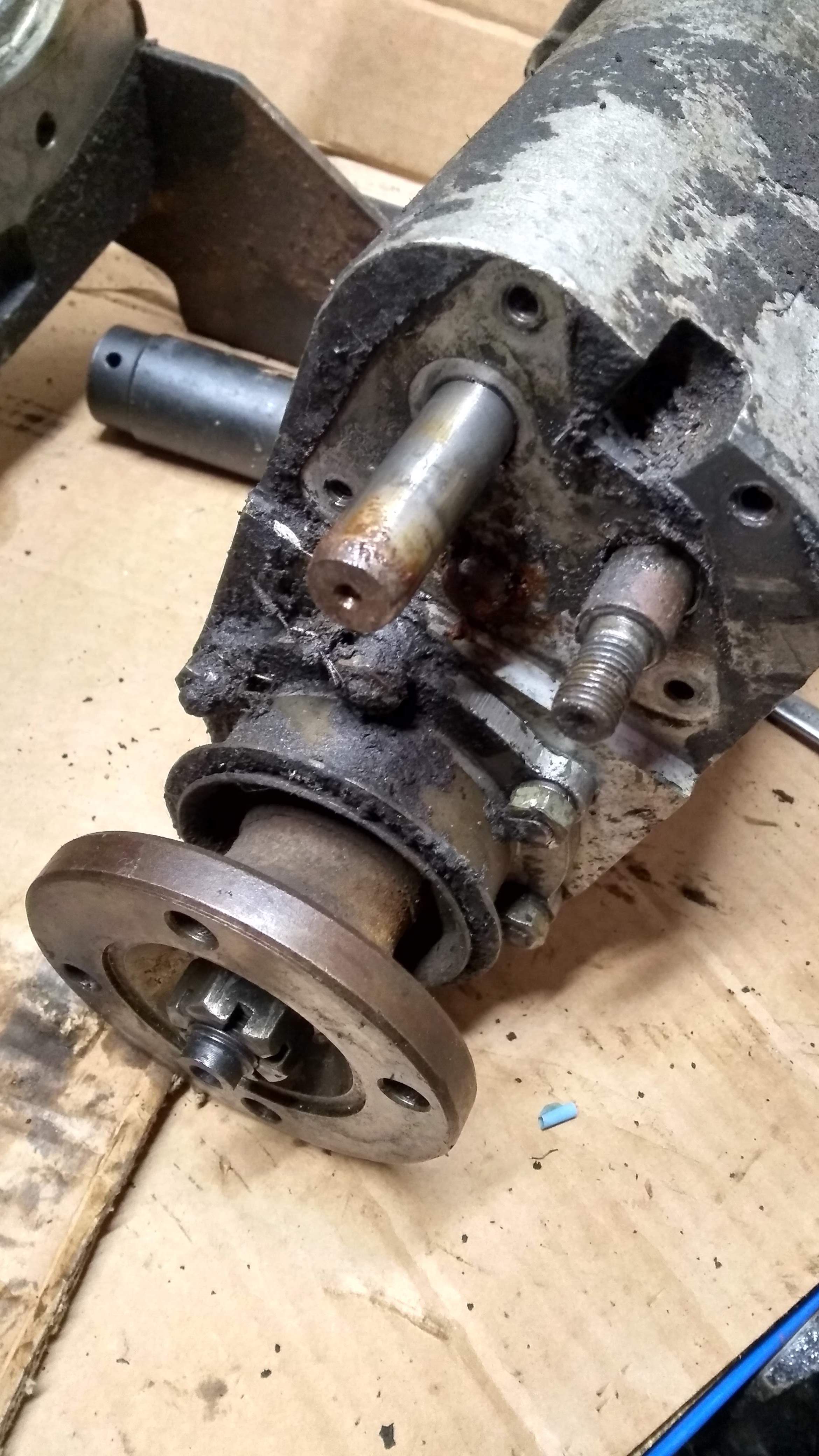
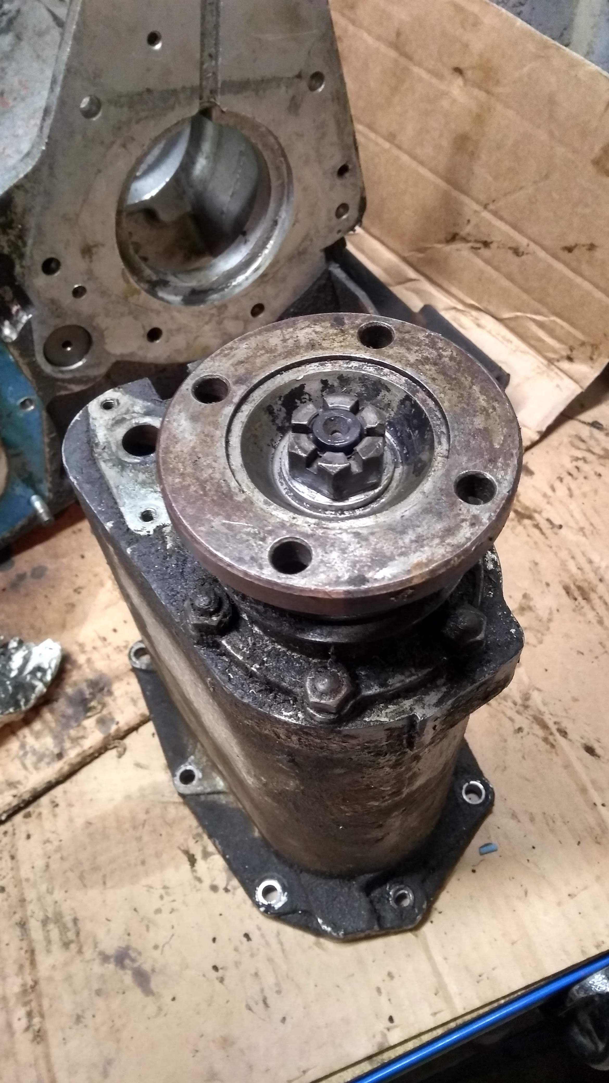
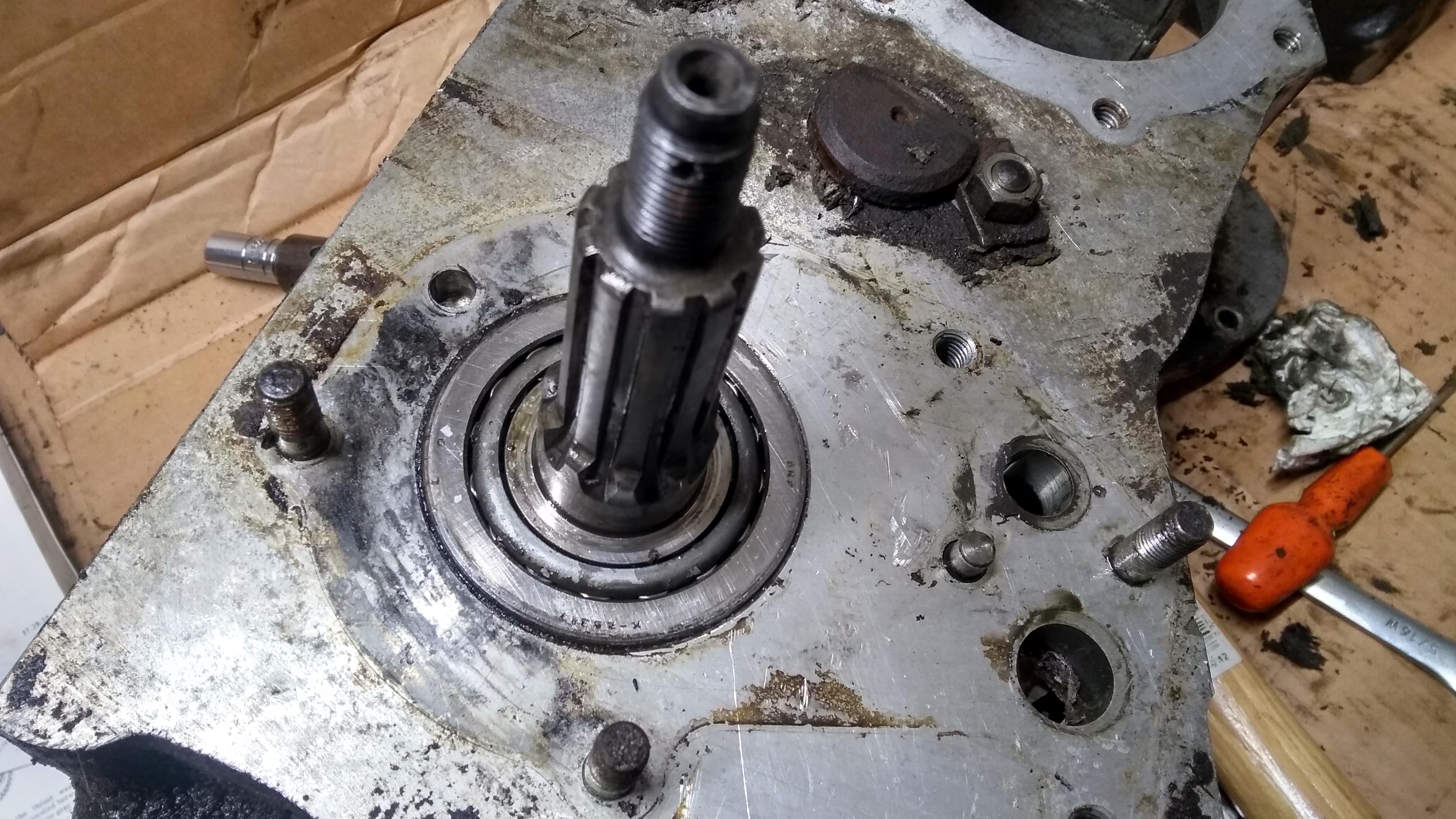
Next up is removing the front drive shaft from the housing, this is pretty easy and just requires removing the castle nut from the end of the shaft (I pre loosened this when it was all together), the front drive flange will then slide off and the shaft can be pulled out. The oil seal retainer can also be unbolted to reveal the bearing.
Then I needed to remove the remaining studs from the front of the housing so that it could sit flat for the bearing being pressed out. This was pretty easy with the double nut method. You just need to screw one nut on as far as it will go, then tighten it up slightly, then thread another nut on until it butts up against the lower one. Tighten it up slightly, at the point you should see the stud move. Then undo the stud using a spanner on the bottom nut.
To remove the nuts from the stud, I put it in a vice and then undo them with a spanner. The vice has aluminum sheet in front of the jaws to protect the threads.

The last bit to remove is the speedo housing, this is also fairly simple and just requires removing the nuts and studs like above. I did have a couple that wouldn't budge with the spanner and required using the breaker bar.
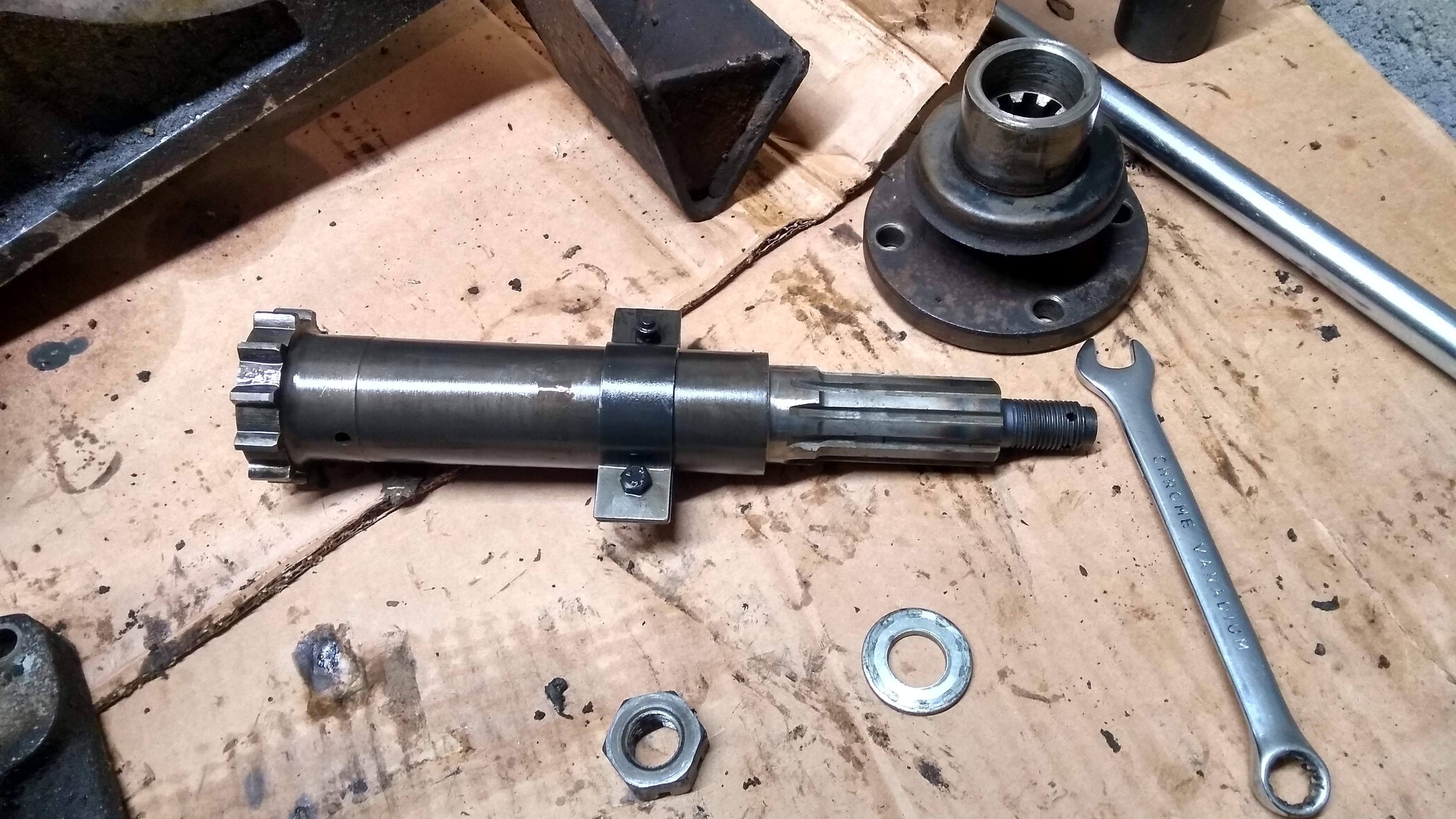
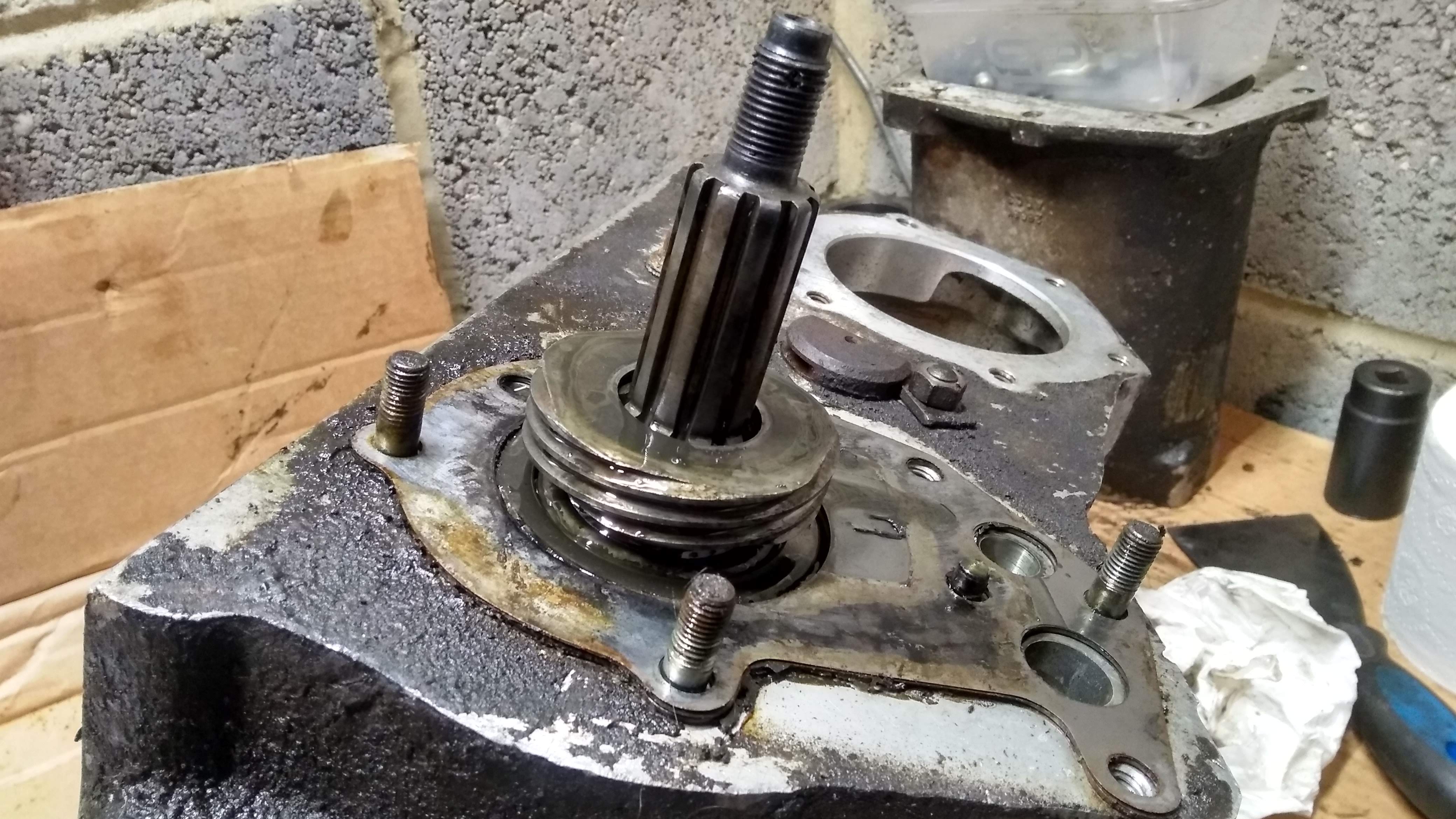
With the housing removed, you just need to slide the worm gear off the shaft and also remove the shims that are used to set the preload for the gears.
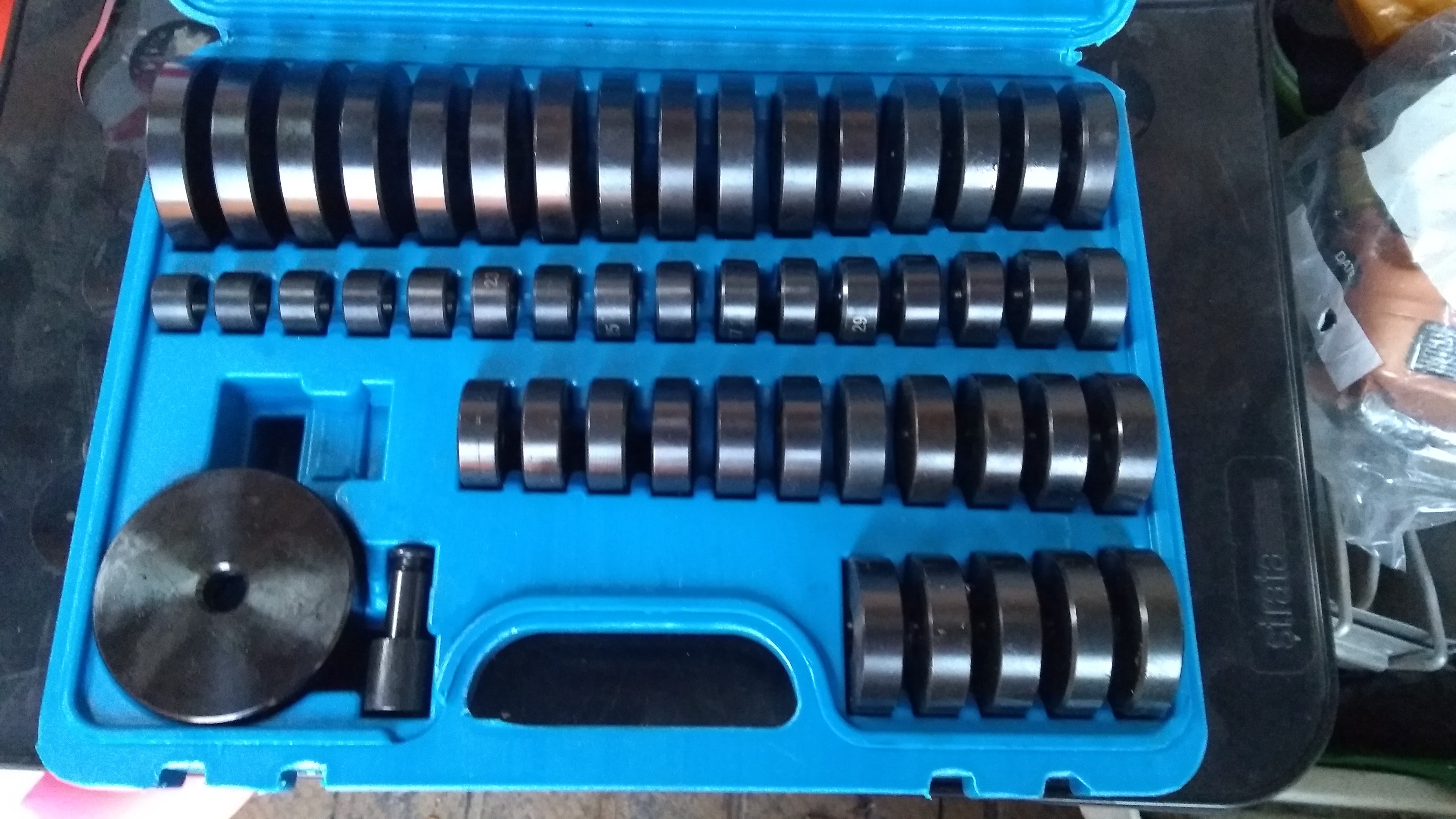
The last part of the disassembly (that wasn't the main casing) was to press out the seals and bearing. When I bought the press I also bought a set of pressing disks, they vary in size from about 18mm up to 70 something, they worked great for spreading the load of the press to the thing to be pushed out.
First up was the front output oil seal.
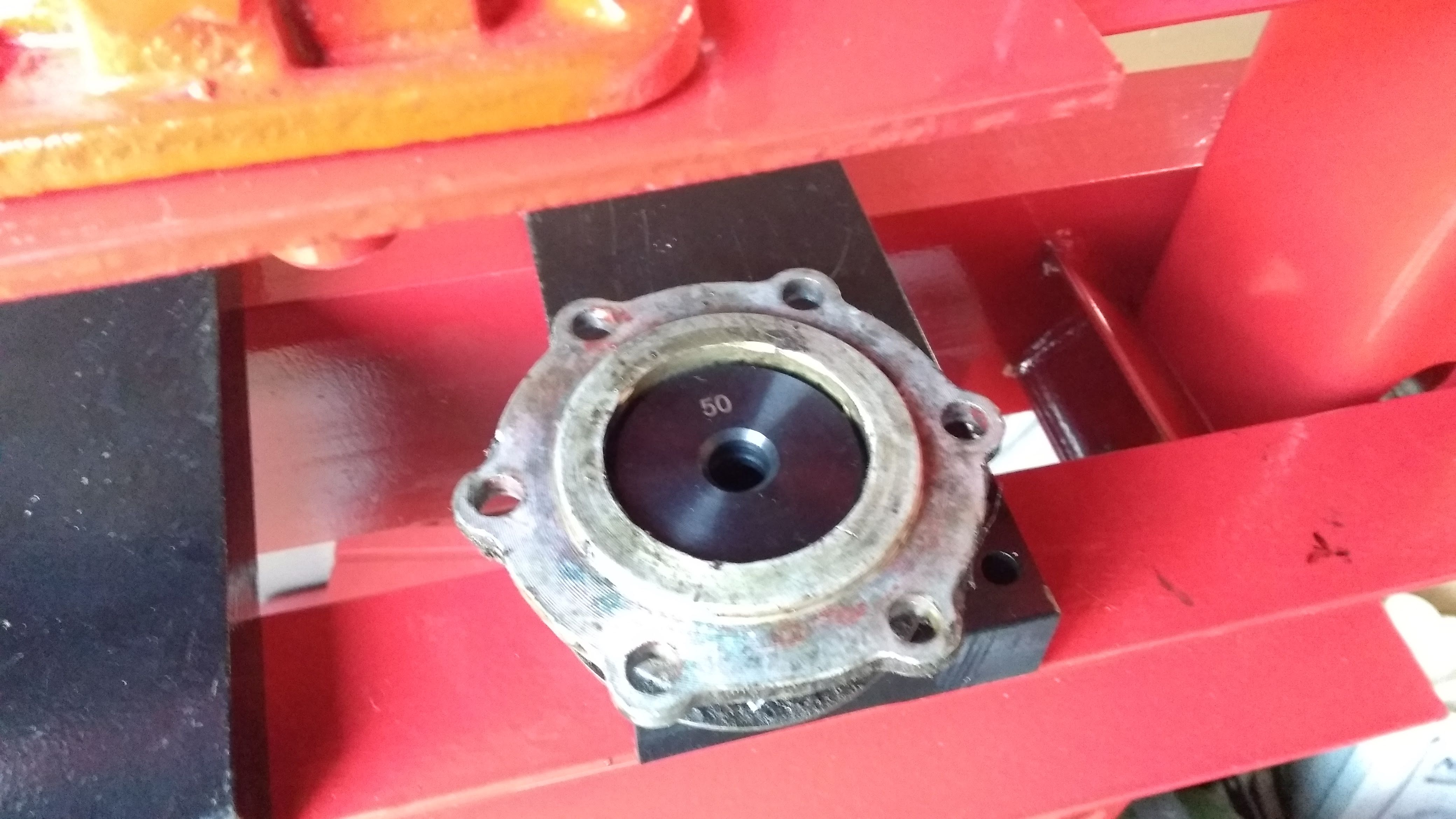
Then the rear output oil seal from the speedo housing. I had to use pressing disks in decreasing size to raise the height to where the press would reach it, worked well though.
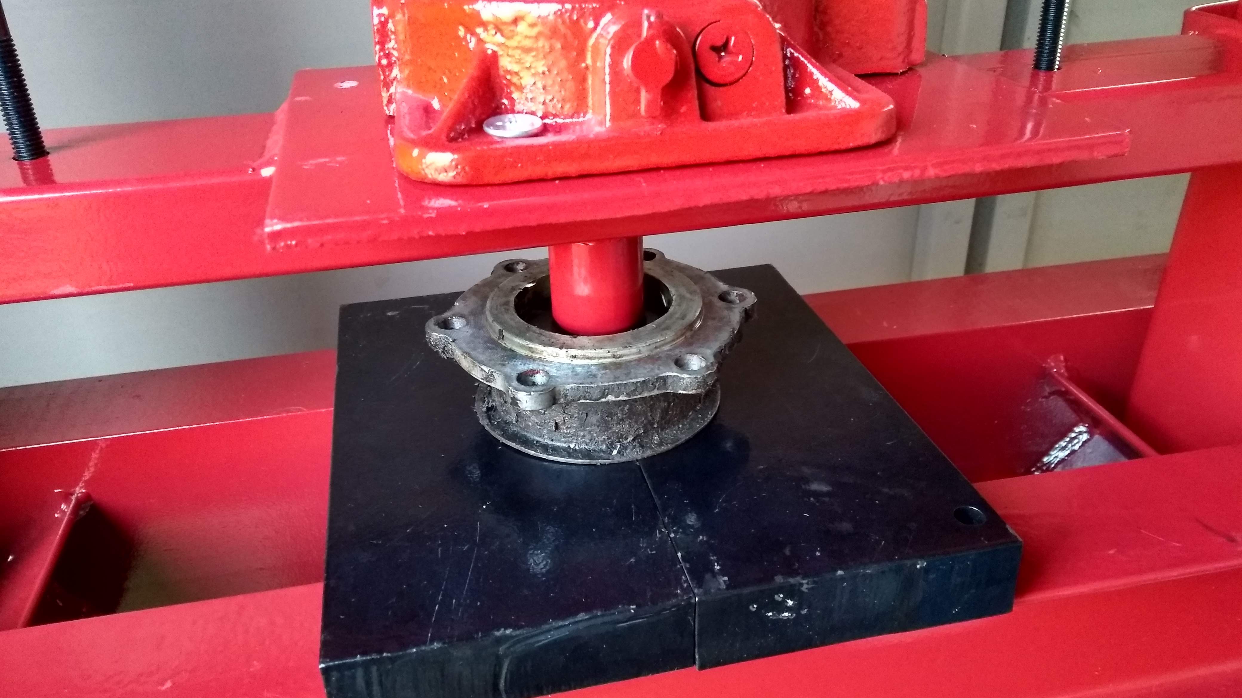
Lastly was the bearing for the front output shaft. I used a pressing disk and an extension from my socket set for the press to push on to reach it.
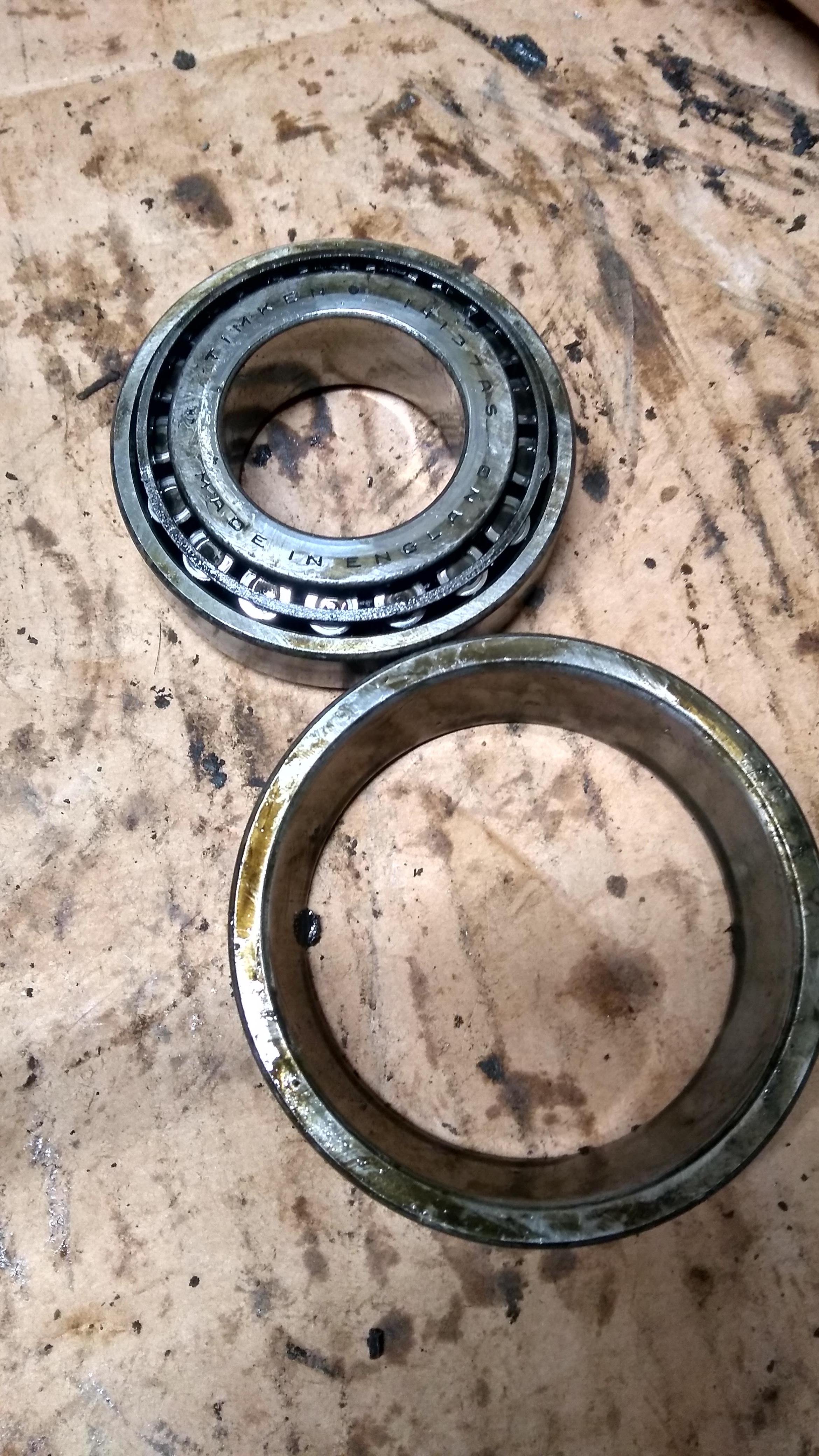
The bearing on it's way out
Bearing freedom! It does feel pretty gritty when you turn it by hand, so probably good it's being changed.
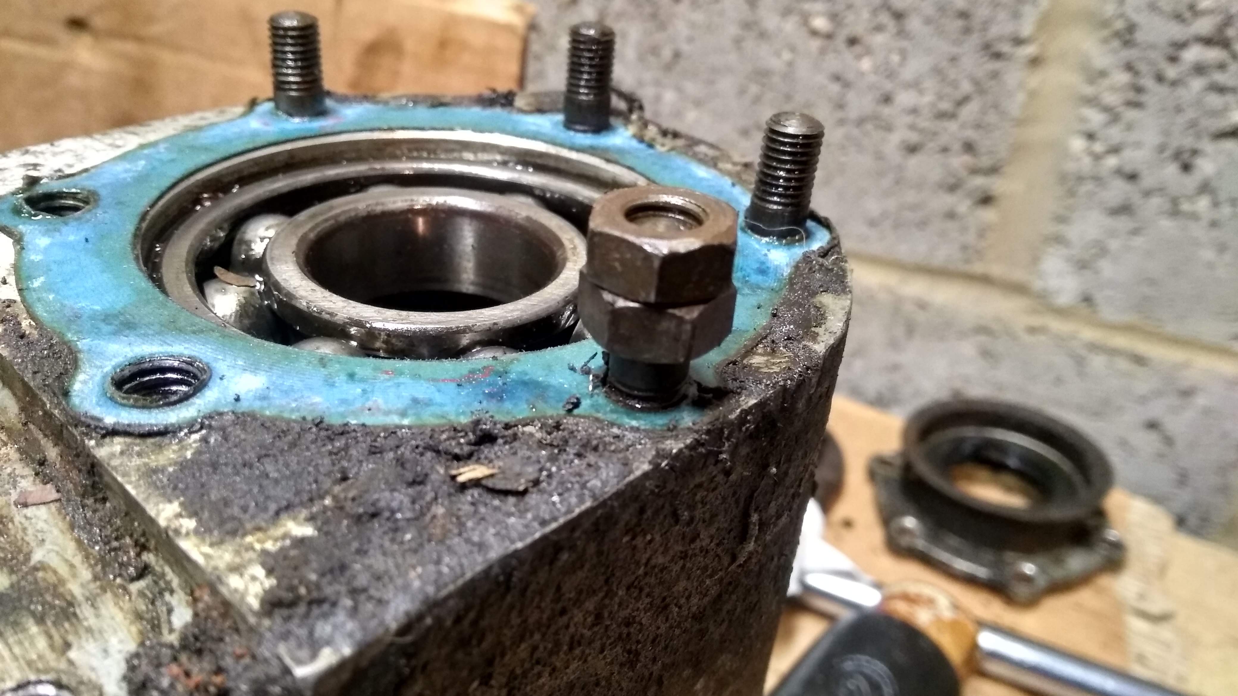
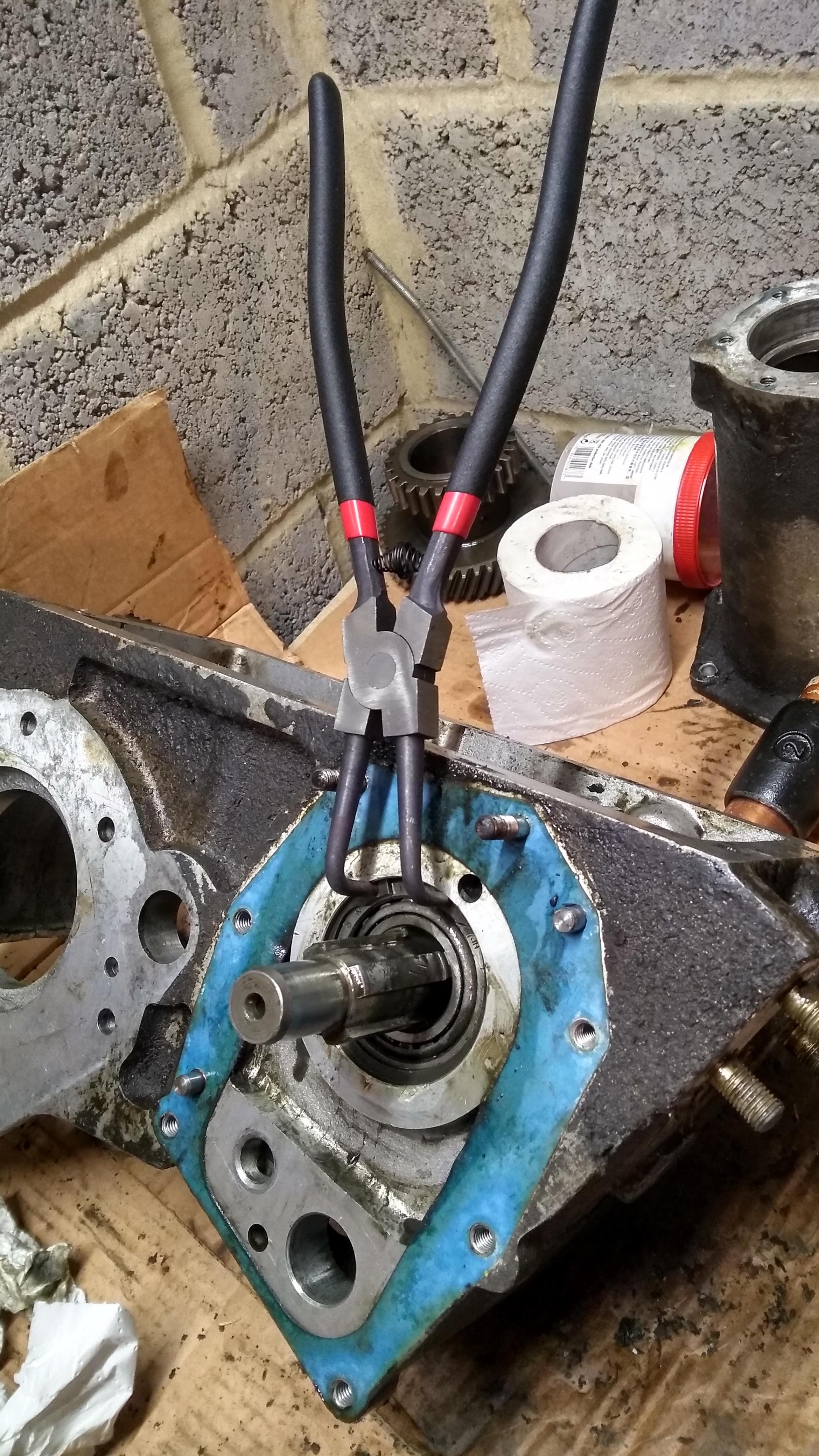
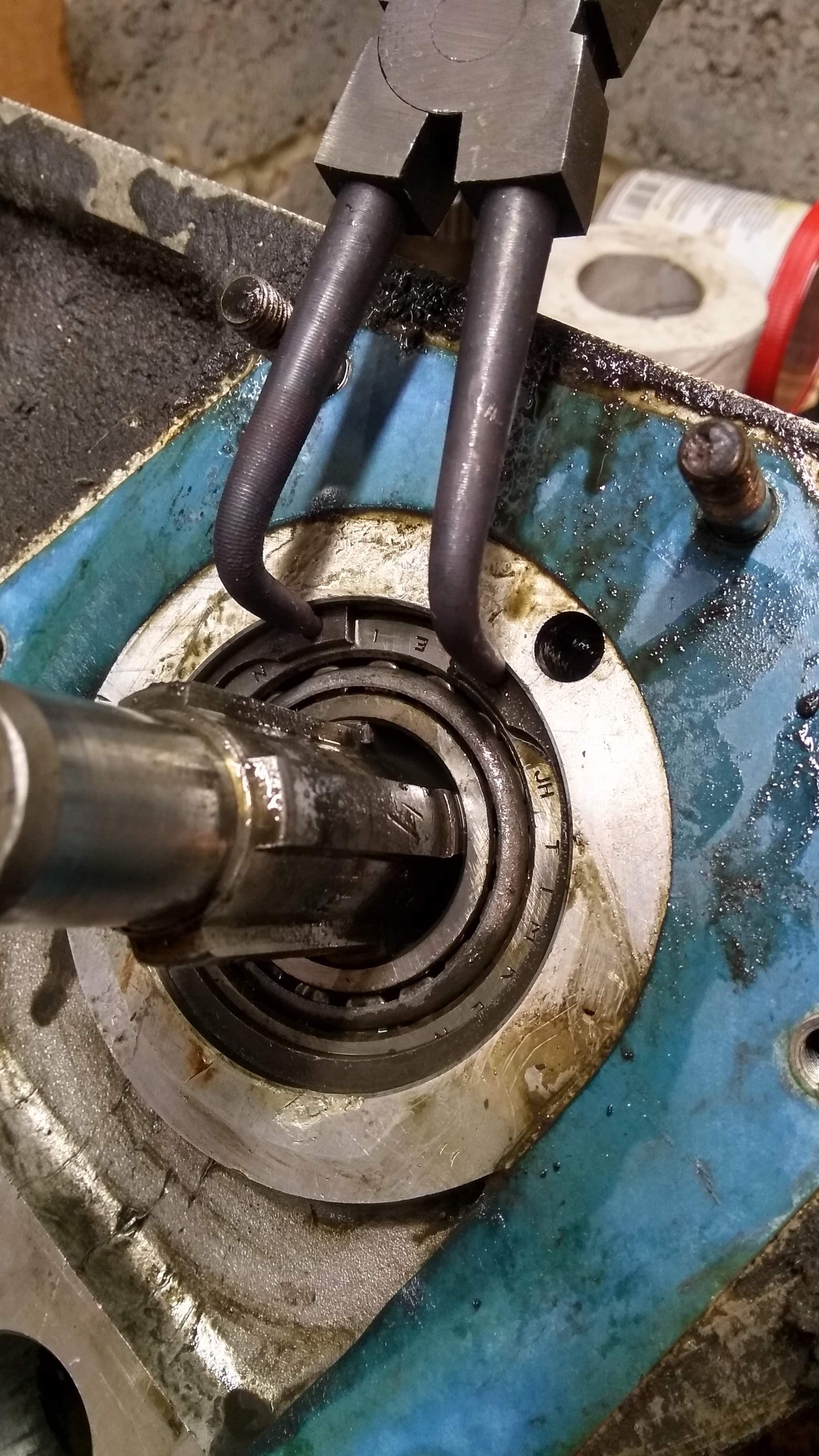
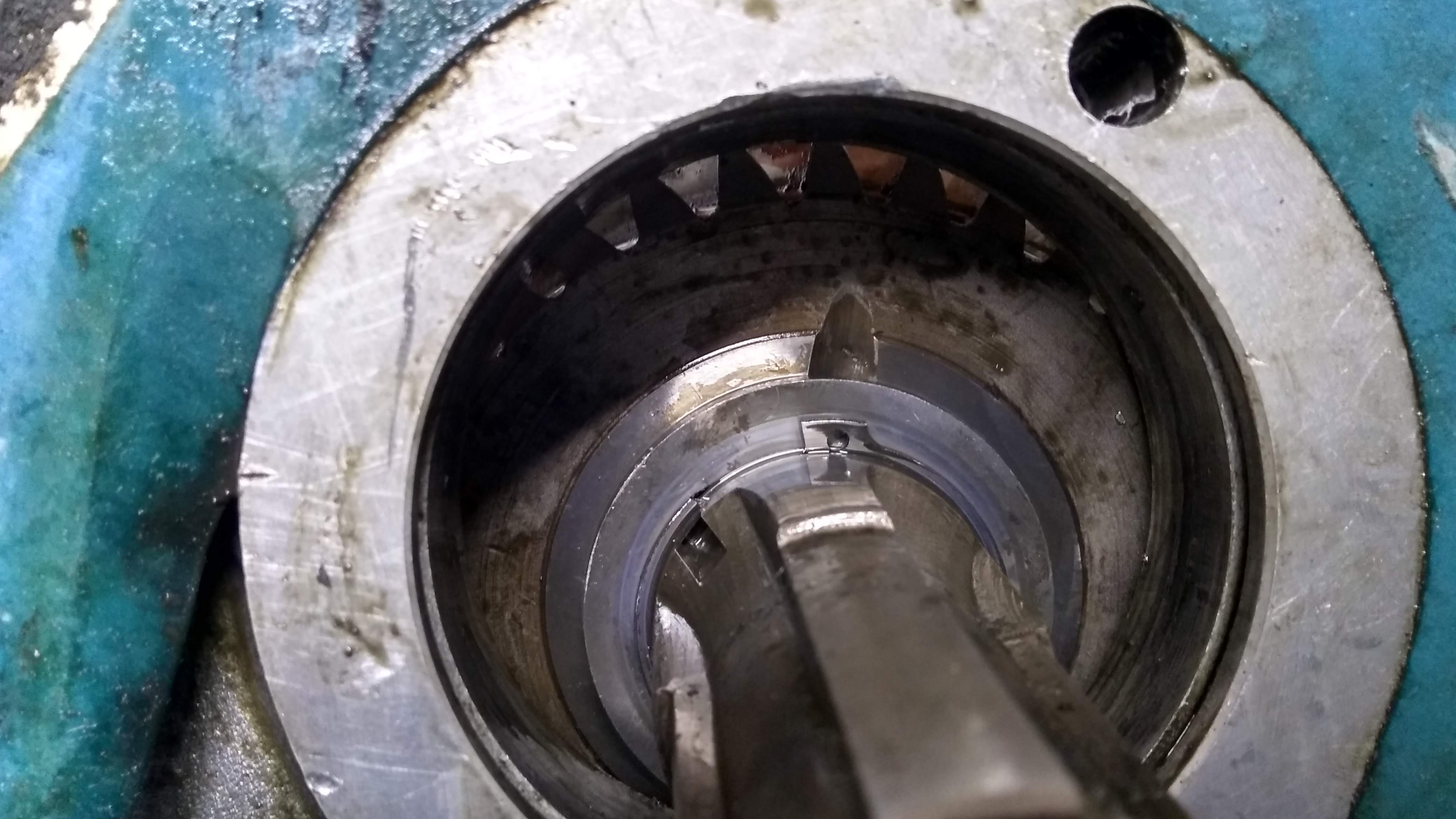
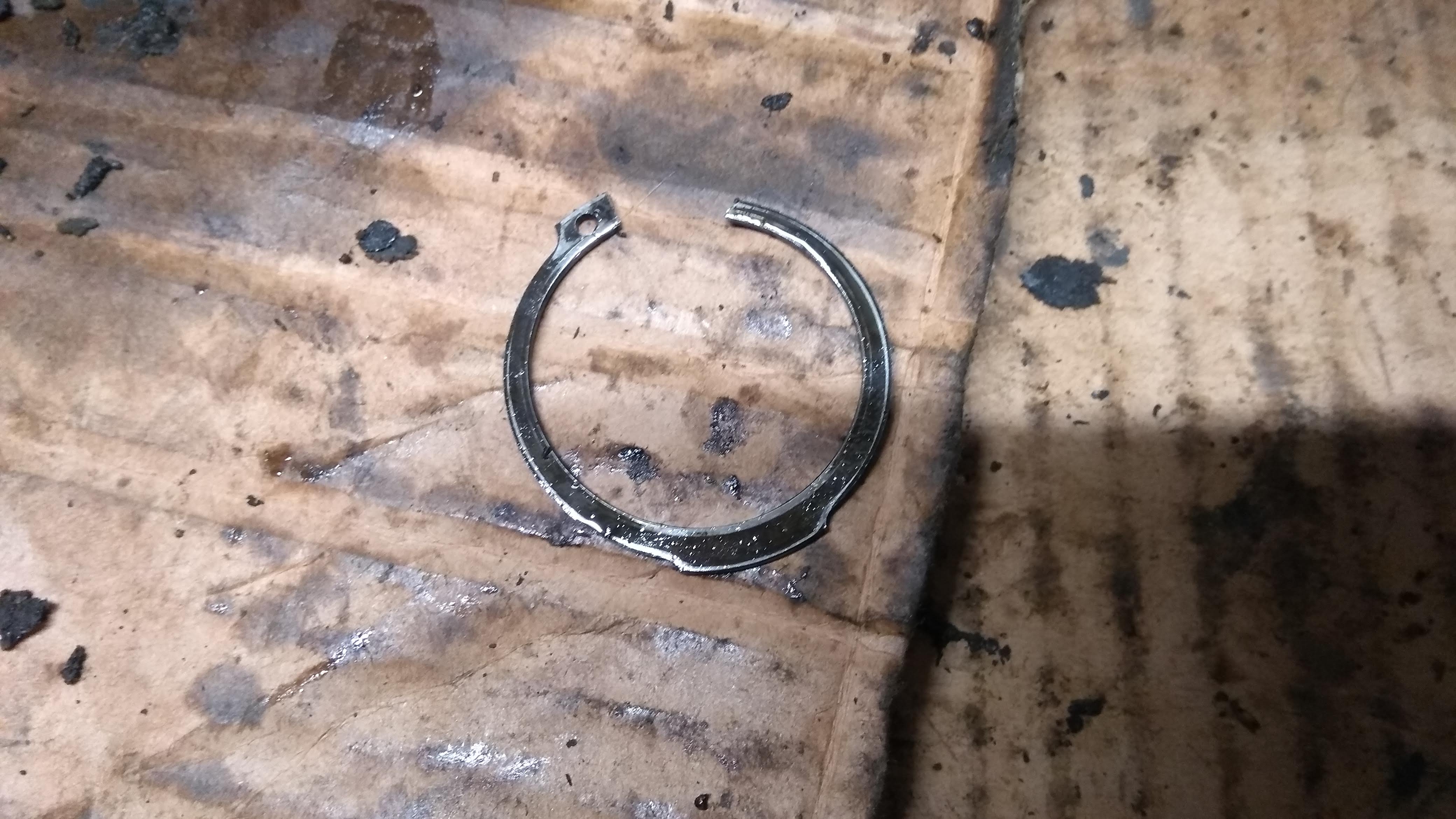
Onwards to the main casing, firstly remove the massive circlip that retains the front bearing. This is where buying massive circlip pliers comes in handy.
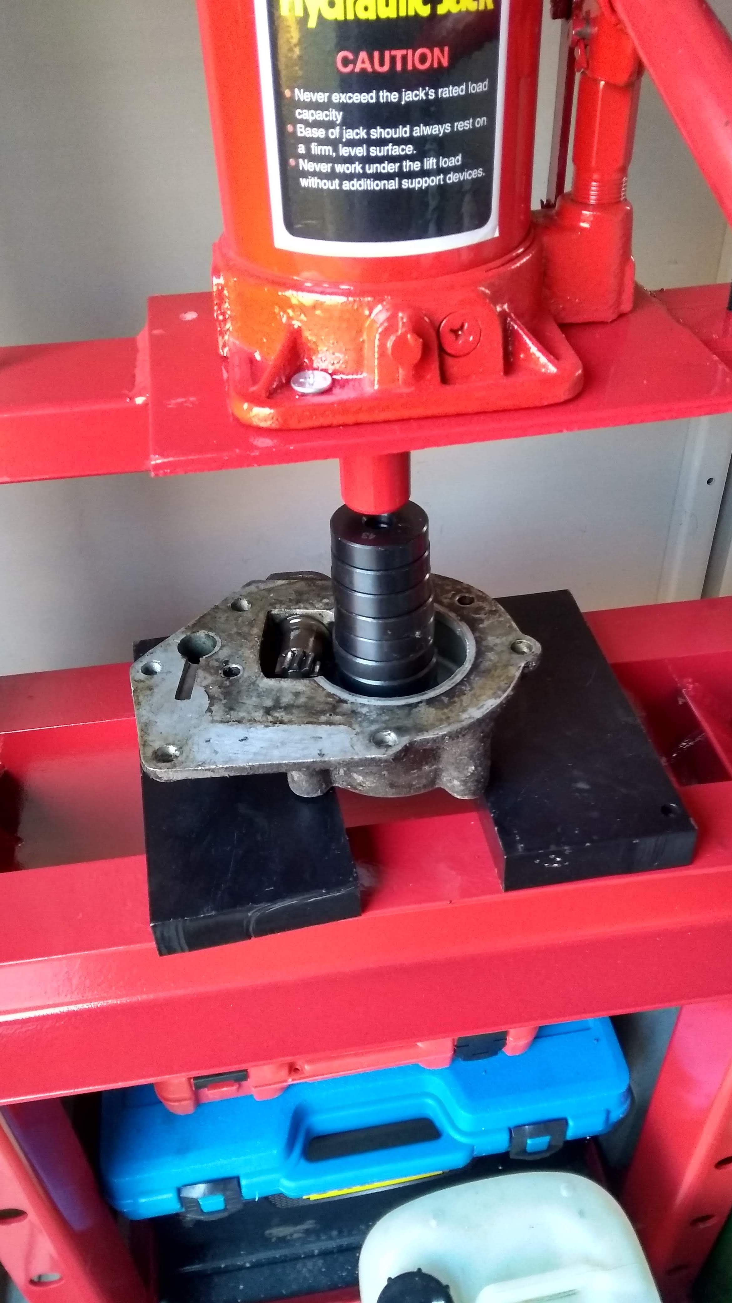
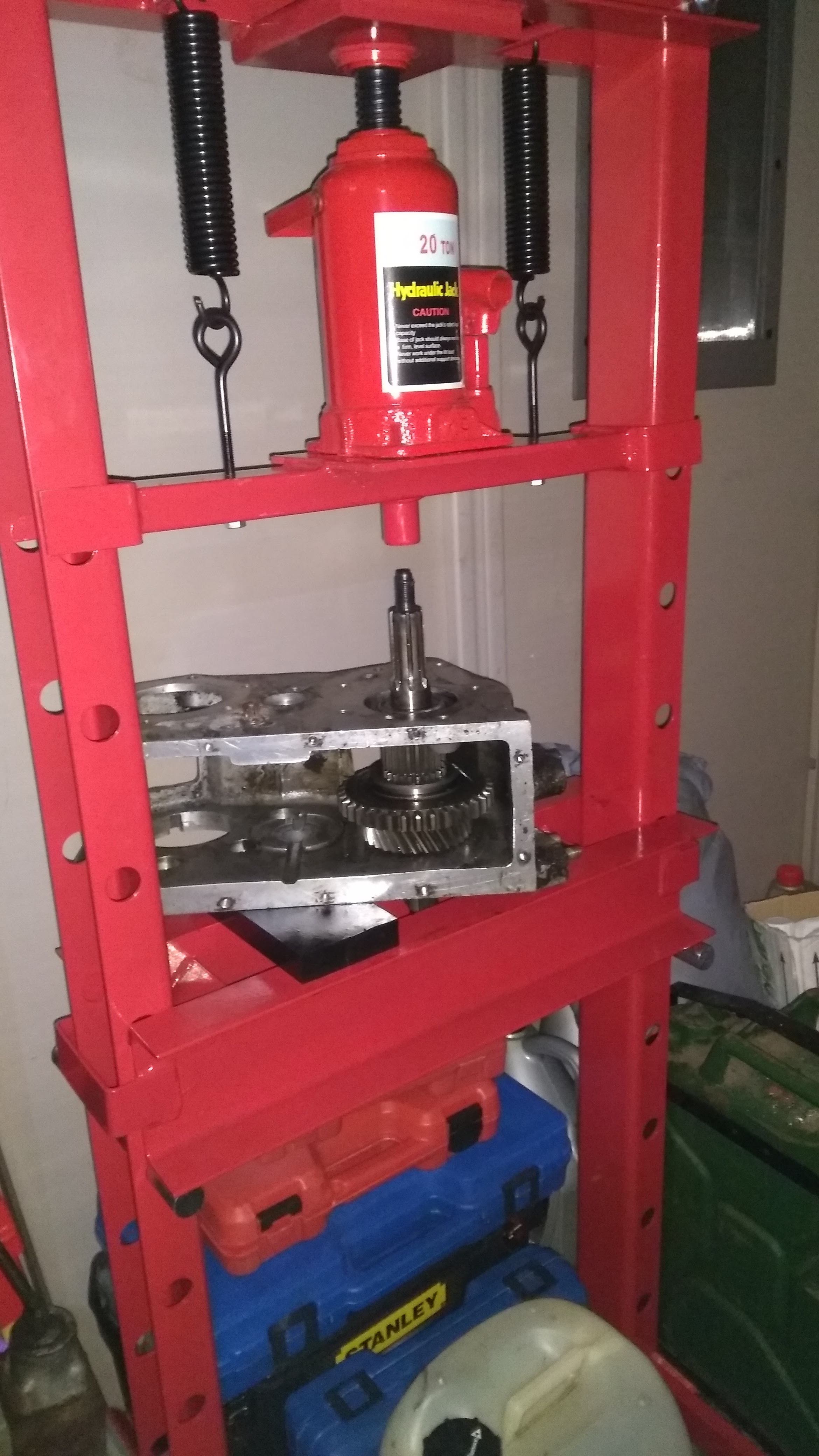
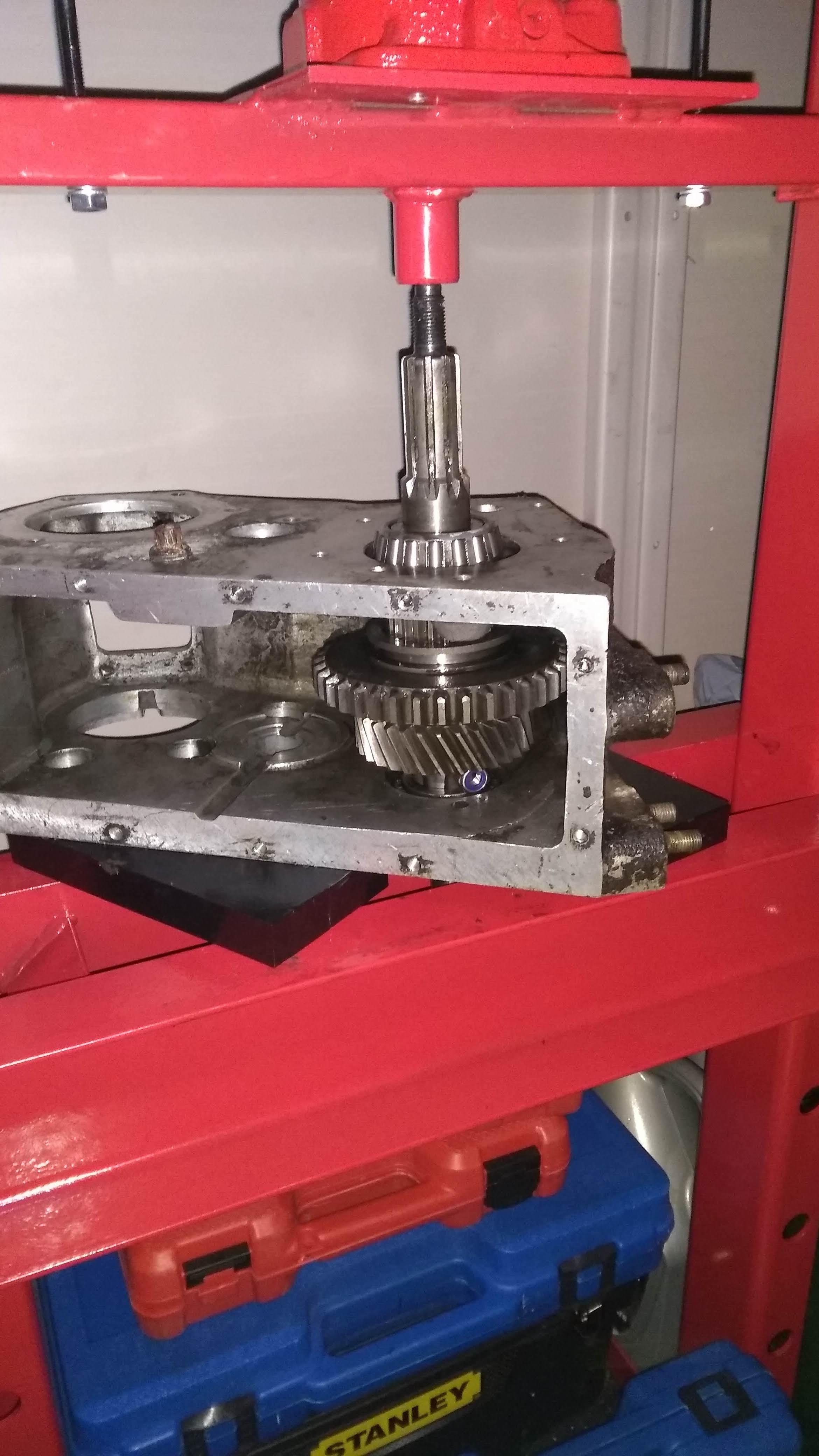
The book then says to drive the shaft towards the rear until the bearing race is pushed out, I did try with the mallet but after a few hits it wouldn't budge so I took it up the the press in the shed. Pushed it out really easily.
Once the bearing race has fallen out, the case was then flipped over and the shaft pushed as far as it would go the other way. Until the gear butts up against the case.
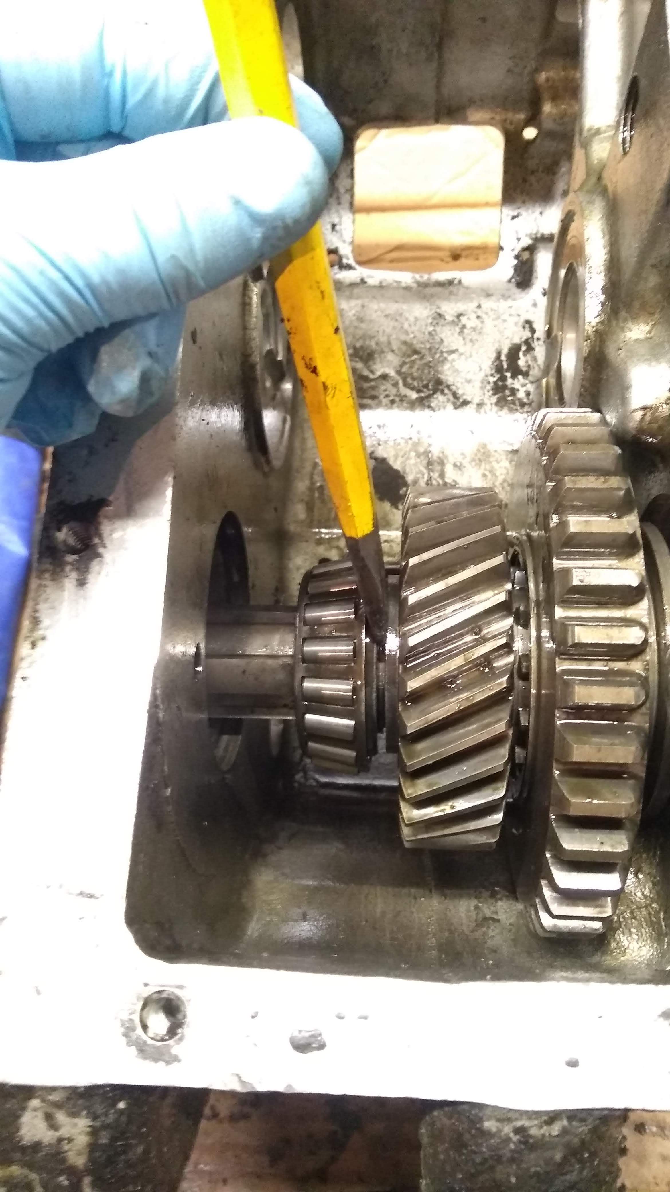
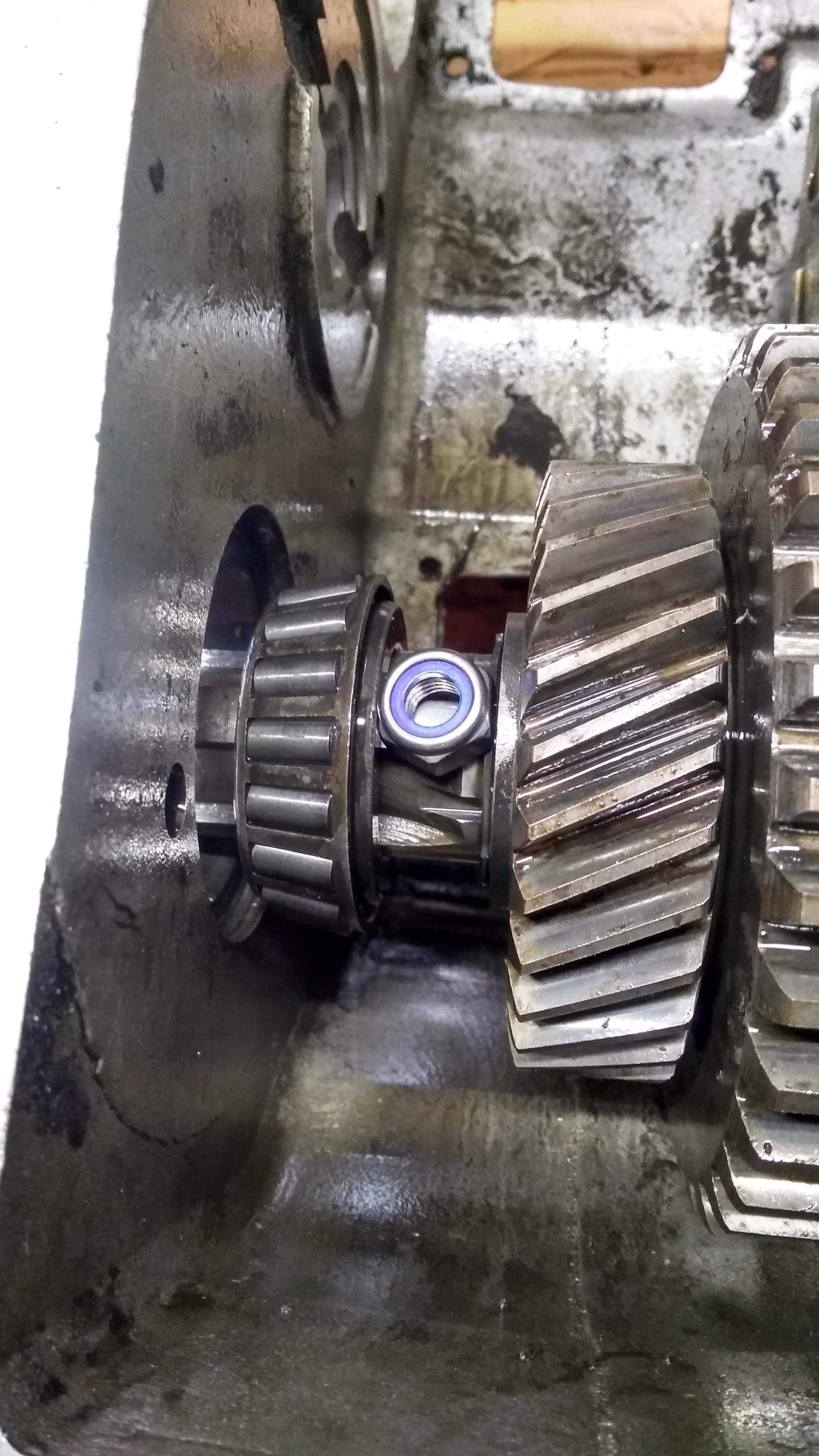
Then it was back to the garage to prepare to remove the final bearing race. The book says to use a packing piece between the roller bearing and the race. They suggest using an old bearing race cut to size, which isn't useful if you are doing it for the first time. What I've found works (from doing the previous case) is to split the bearing away from the shaft. To do this place a chisel between the bearing inner race and the thrust washer and gently tap with a mallet, this will allow you to then pry the bearing away from the washer.
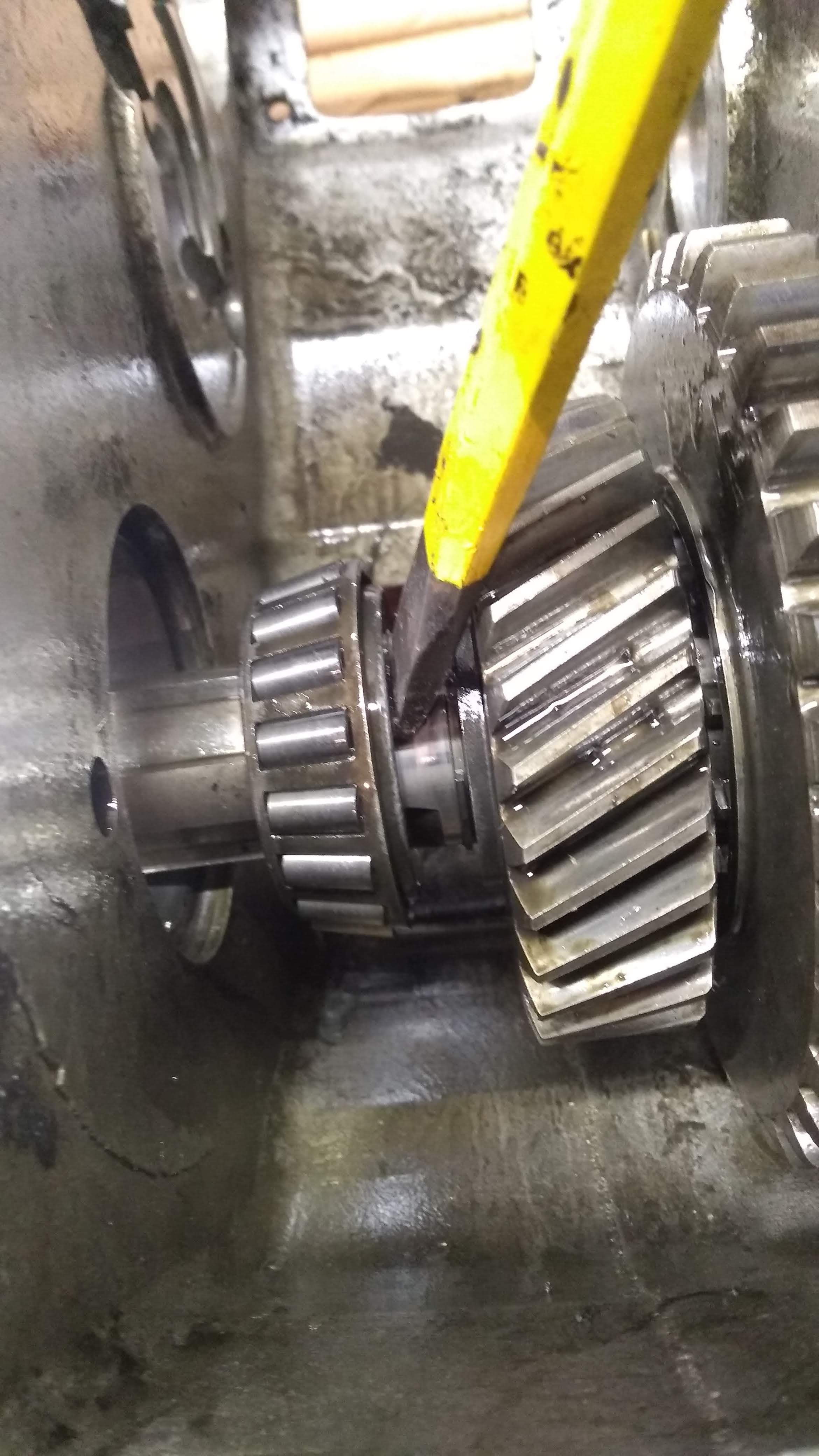
You can then fit a M10 nut in between the race and the washer. I found it works ok with one, but two would be best if you manage to get them to not fall out. Push the inner race up against the outer and tap the rear shaft with a mallet to wedge the nut tightly between the pieces. Then press the race out.
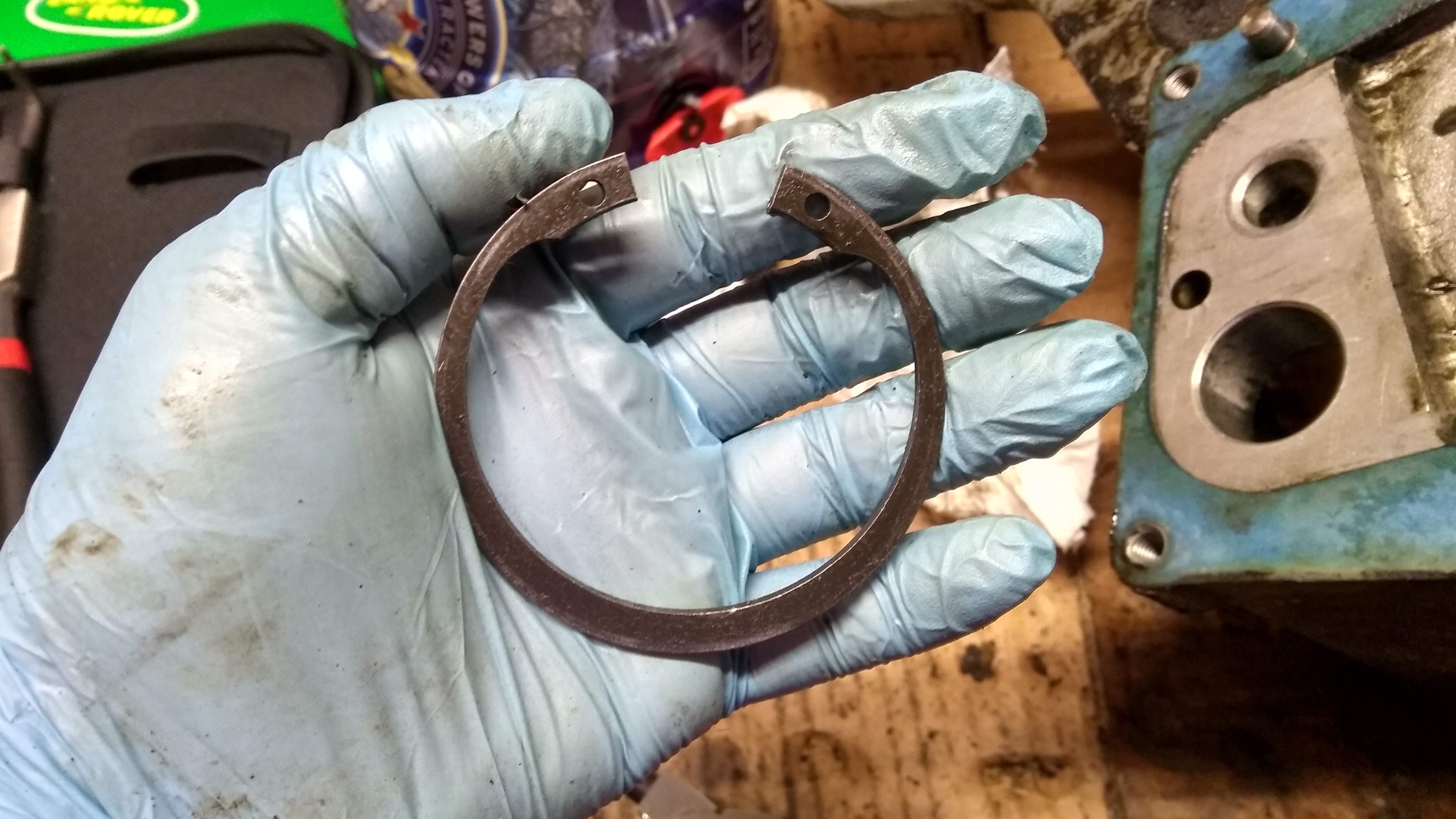
With the race removed the inner race can be pried off the shaft and then the next challenger is revealed. The circlip that holds the thrust washer in place. Safety squints engaged. You might be lucky and it has both eyes and can be easily removed. I have been unlucky on both occasions. On the first casing both eyes were missing and it took lots of trying to lever it up and away, and it snapping back in place before I was able to finally get it off. This time one eye was missing, so I was able to lever the bit with the eye out of the grove with smaller circlip pliers and then the rest of it using a couple of flat head screwdrivers, it only snapped back in place twice.
With the circlip removed, the thrust washer can be removed and then the shaft can be removed rearwards through the gears.

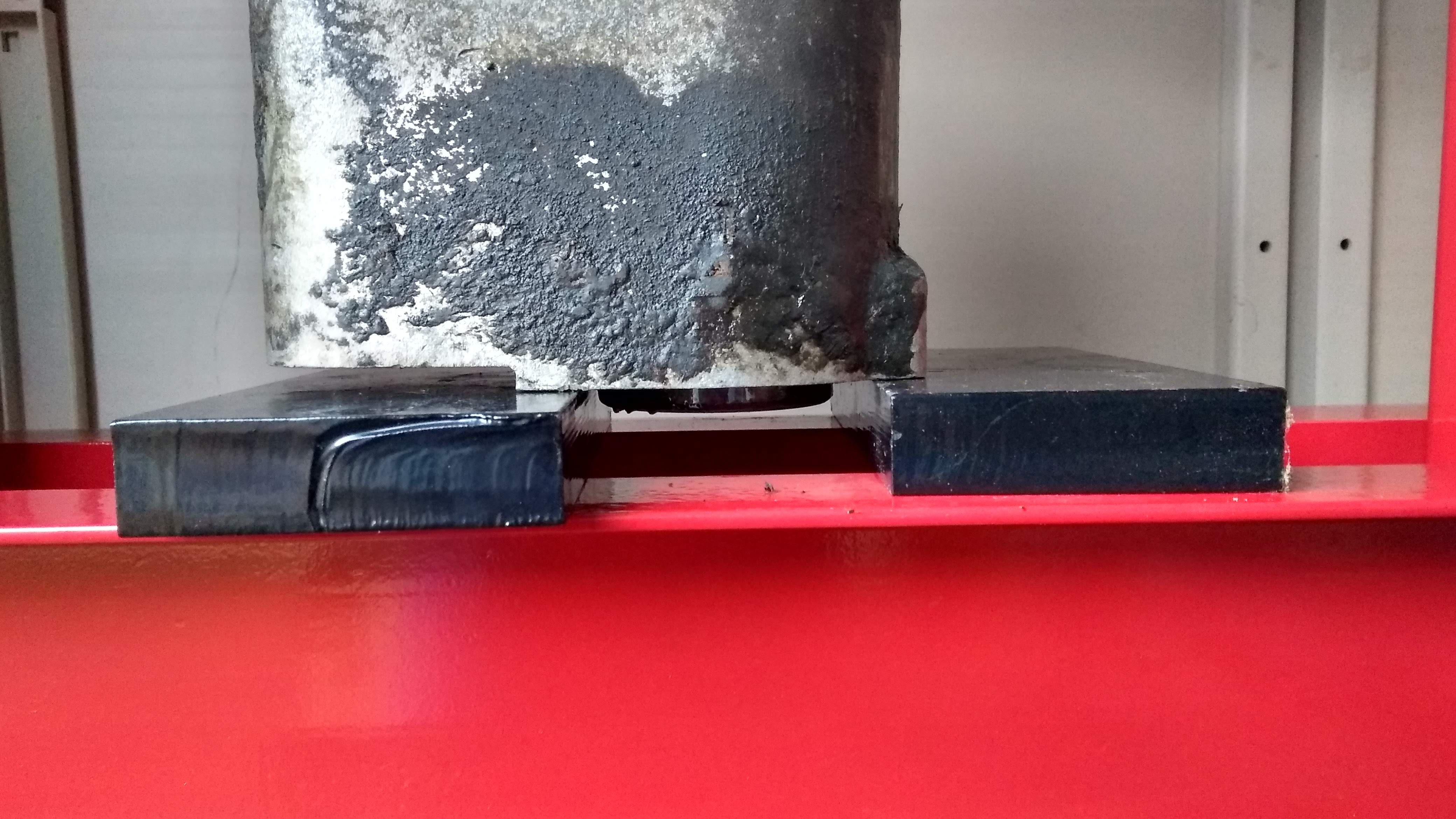
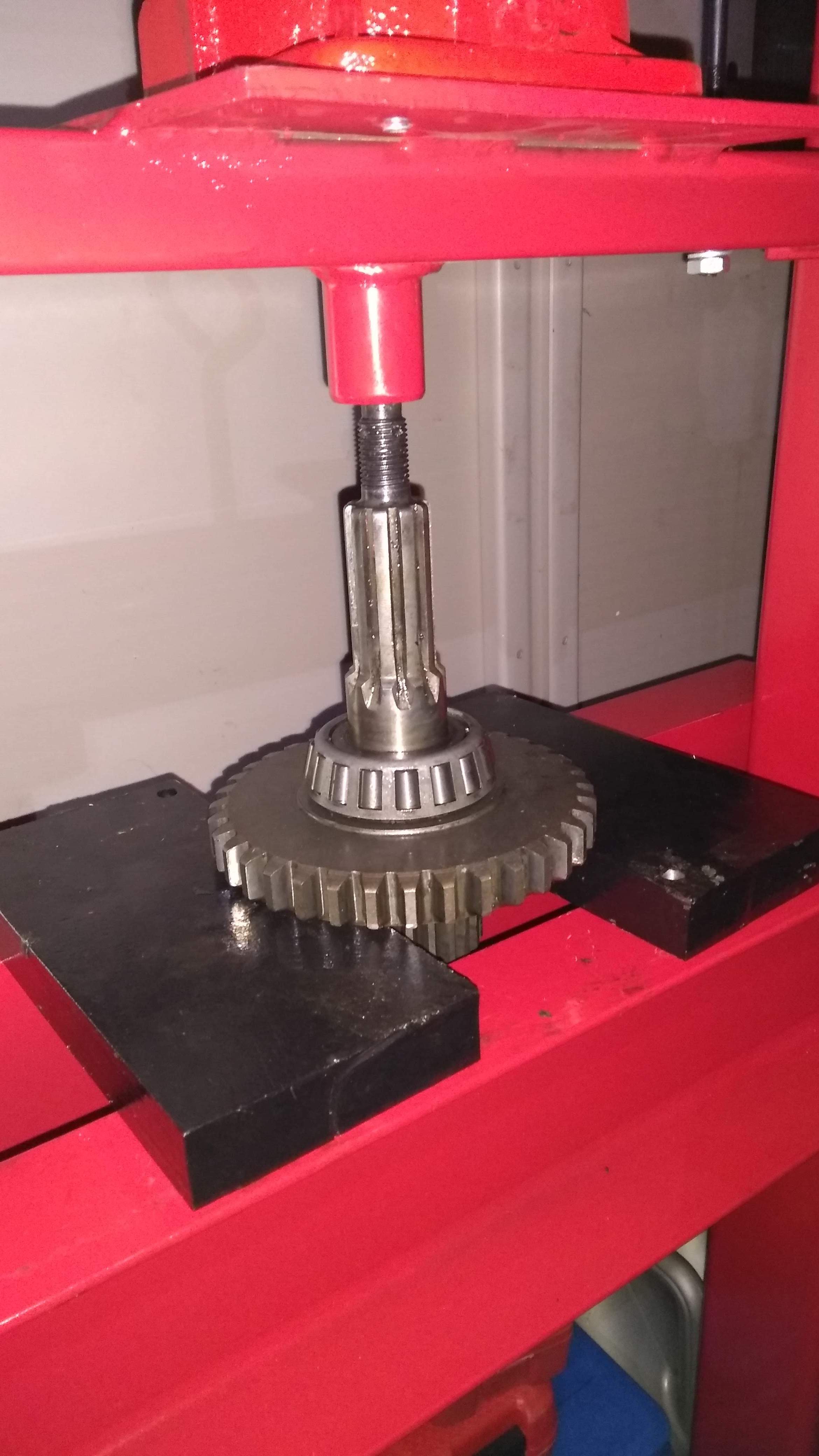
The last thing to do is to press the rear inner bearing race off the shaft, this is what caused me to buy the press originally. The low gear is used as a block to push the bearing off. You have to hold the shaft as you press, to catch it when the bearing comes off, else it will just drop. It's heavier than you are expecting at the time.
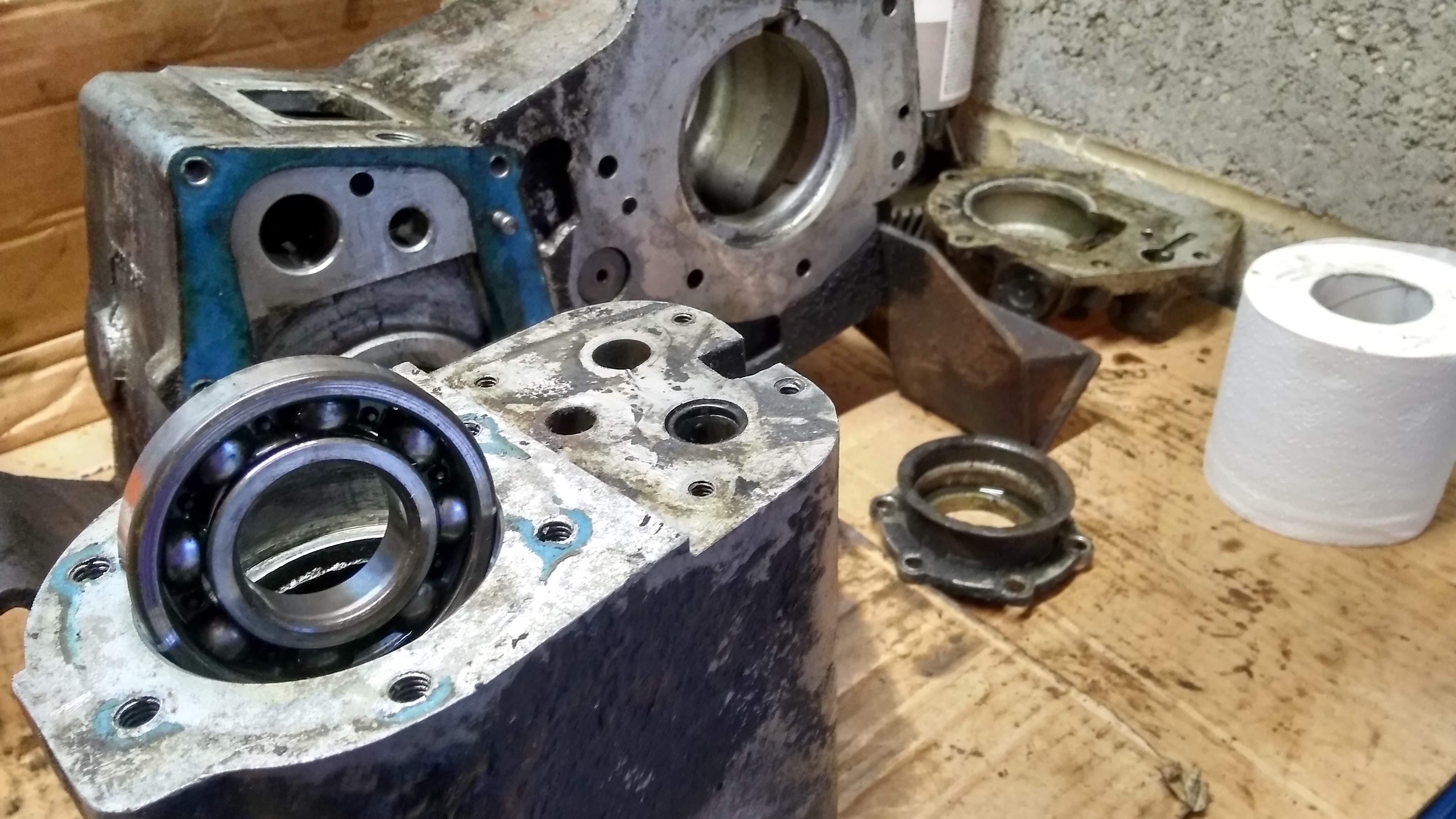
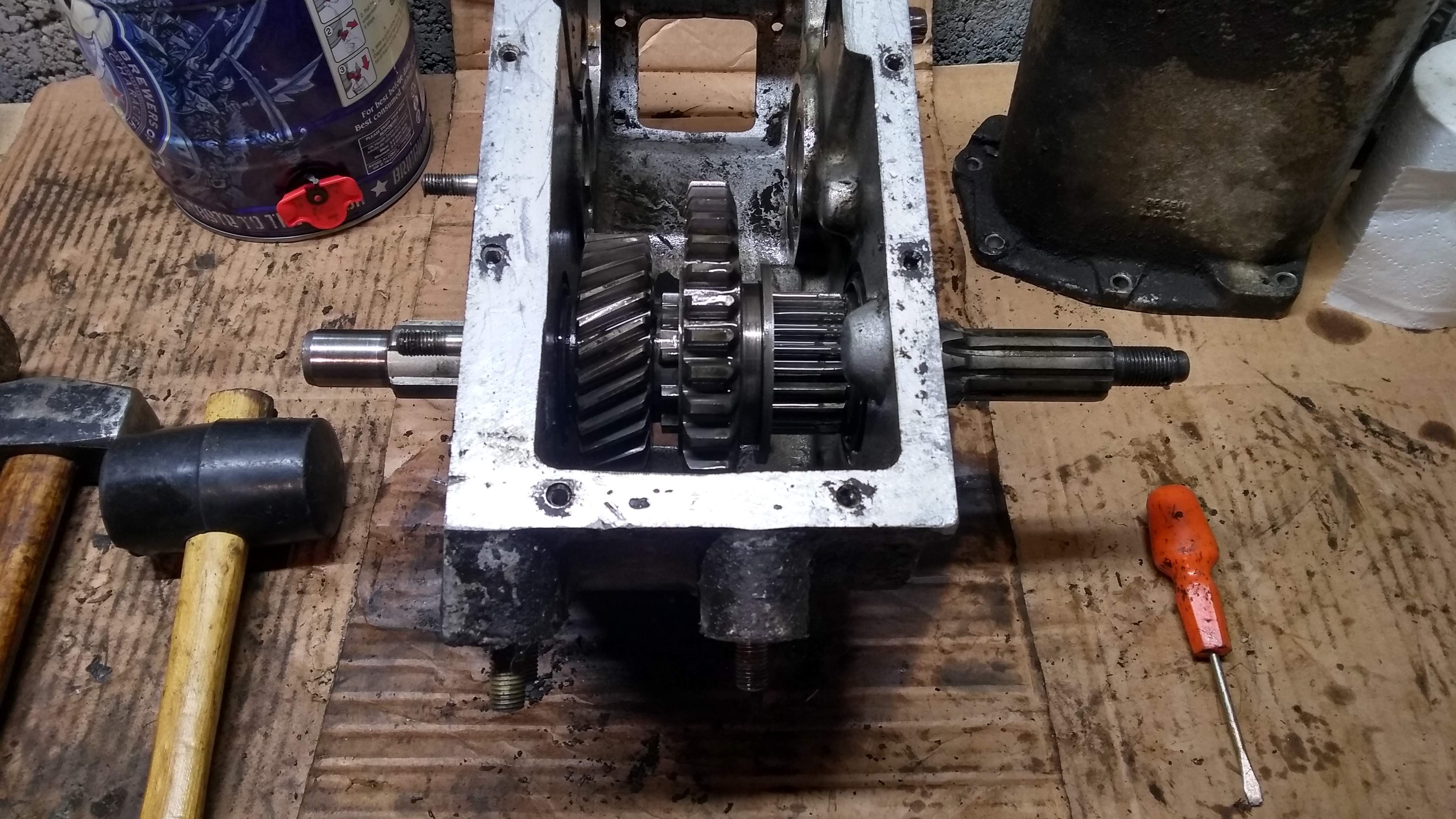
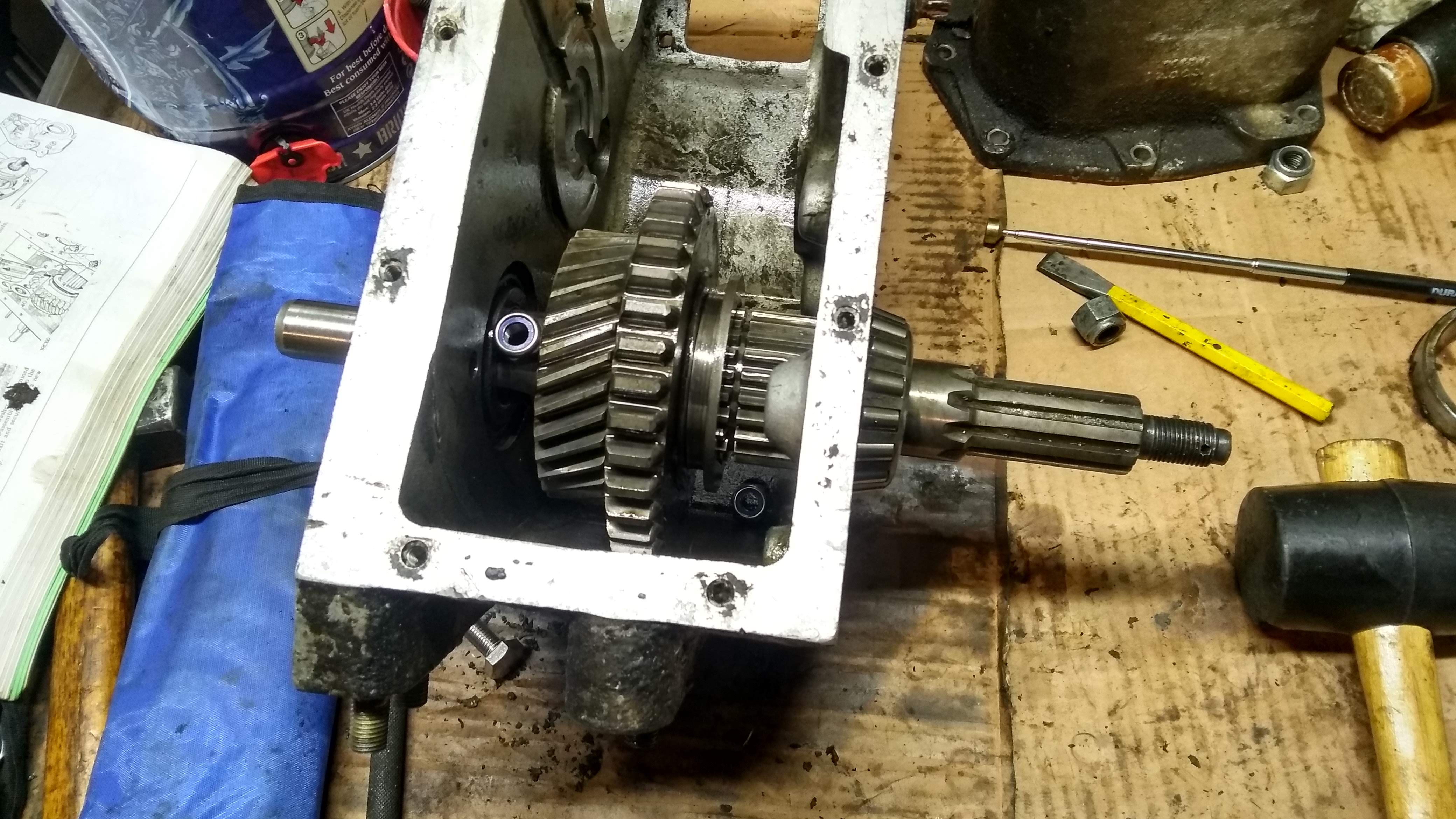
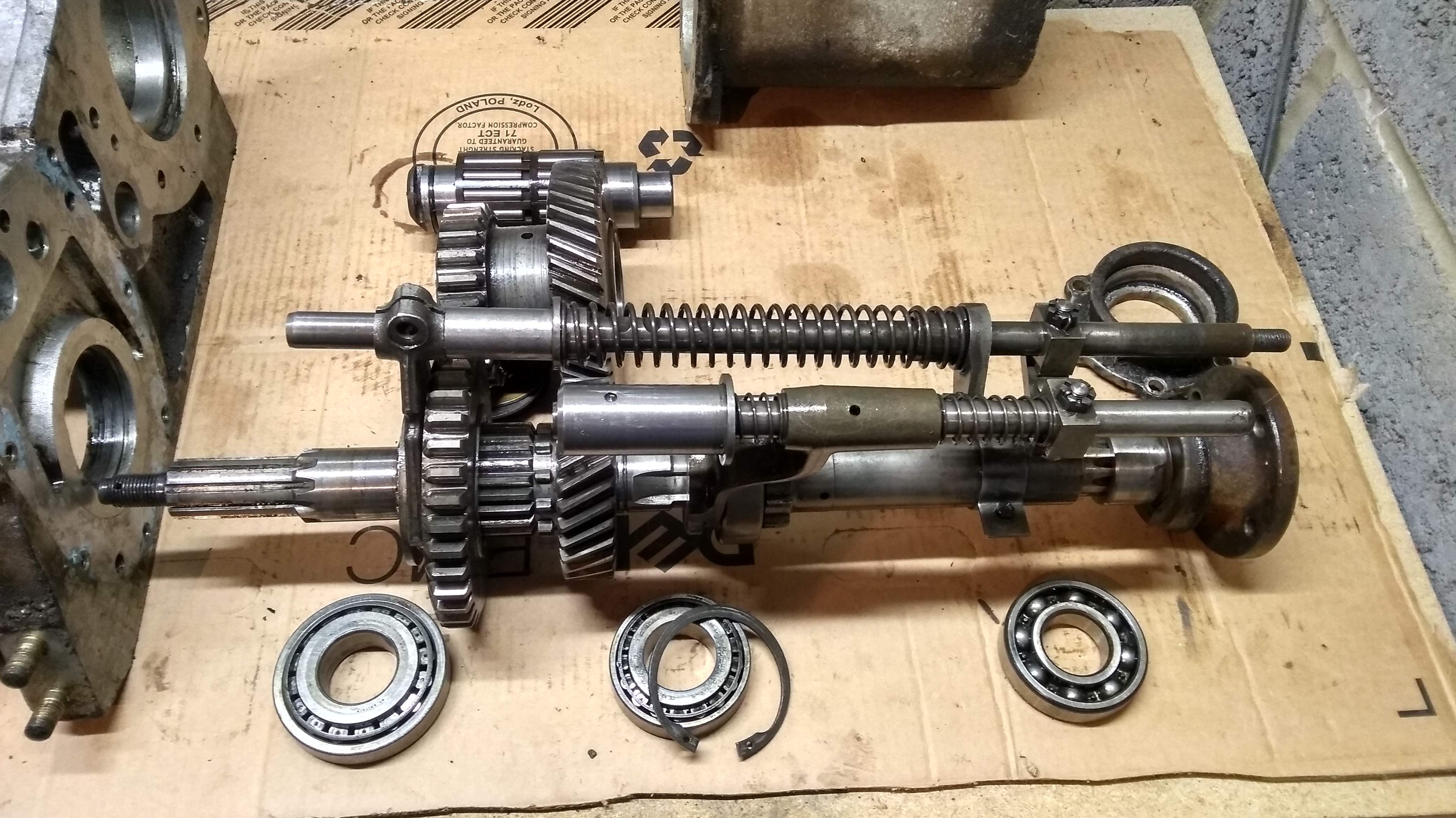
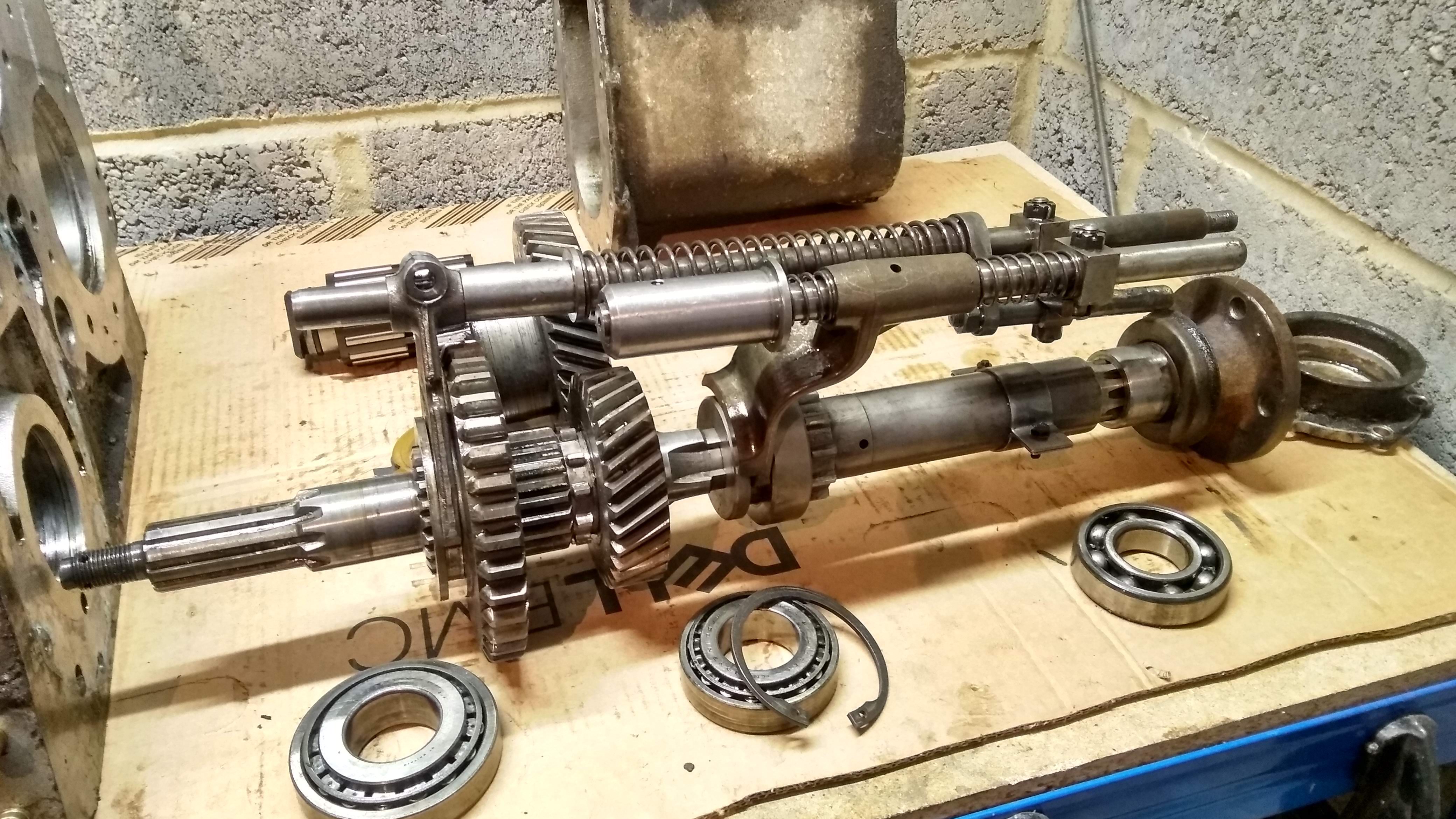
The complete innards reassembled on the bench, as how they would be inside the casings.
And everything packed away ready for the next step, which will probably be degrotting of all the parts.